Tesla Model 3: Contactor - Fast Charge - HV Battery - Install
Install
- Use IPA wipes to clean the high voltage mating surfaces of the fast charge contactor and the positive and negative DC link and DC input busbars.
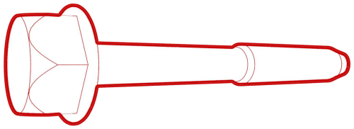
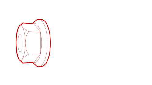
- Install the HV battery fast charge contactor to the insulator.
Note: Align the 2 guides as the fast charge contactor is installed on the insulator.
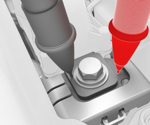
- Install the bolts that attach the fast charge contactor to the insulator,
and then mark the bolts with a paint pen after they are torqued.
 Torque 5.5 Nm
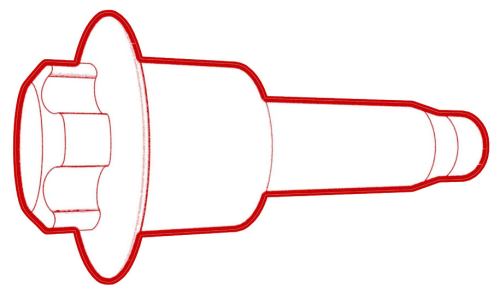
 - Install the positive and negative inlet and DC link busbars to the fast
charge contactor, install the new bolts (x4) that attach the busbars to the
contactor, and then mark the bolts with a paint pen after they are torqued.
 Generic Measurement - Actual busbars and fasteners might appear
different
Generic Measurement - Actual busbars and fasteners might appear
different
- Use the Hioki resistance meter to measure the resistance between the positive (LH) HV joint bolt head of the fast charge contactor and the respective positive (LH) inlet busbar, and then the resistance between the positive (LH) HV joint bolt head of the fast charge contactor and the respective positive (LH) DC link busbar.
Note: The maximum acceptable resistance is 0.030 mΩ (30 μΩ) per joint. If the resistance is above this value, escalate a Toolbox session, as appropriate.
Generic Measurement - Actual busbars and fasteners might appear
different
- Use the Hioki resistance meter to measure the resistance between the negative (RH) HV joint bolt head of the fast charge contactor and the respective negative (RH) inlet busbar, and then the resistance between the negative (RH) HV joint bolt head of the fast charge contactor and the respective negative (RH) DC link busbar.
Note: The maximum acceptable resistance is 0.040 mΩ (40 μΩ) per joint. If the resistance is above this value, escalate a Toolbox session, as appropriate.
- Install a new HV battery AC inlet harness to the fast charge contactor. See Harness - AC Inlet - HV Battery (Remove and Replace).
Note: The AC inlet harness is a one time use.
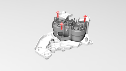
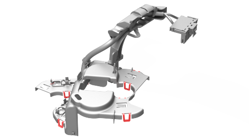
- Install the bolts and nut that attach the fast charge assembly to the
penthouse, and then mark the bolts and nut with a paint pen after they are
torqued.
 Torque 5.5 Nm
 Torque 8 Nm
.png)
.png)
- Install the clips that attach the HV battery penthouse harness to HV battery fast charge contactor cover.
.png)
- Install the DC input assembly to the penthouse, install the bolts (x4)
that attach the DC input assembly to the penthouse, and then mark the bolts
with a paint pen after they are torqued..
 Torque 6 Nm
.jpg)
- Connect the electrical harness to the DC input assembly connector.
.png)
- Install new bolts (x4) to attach the negative and positive busbars to
the DC links and DC input, and then mark the bolts with a paint pen after
they are torqued.
.png) Torque 9 Nm
Torque 9 Nm
Generic Measurement - Actual busbars and fasteners might appear
different
- Use the Hioki resistance meter to measure the resistance at the HV joint between the positive DC input busbar and the positive (LH) fast charge contactor busbar.
Note: The maximum acceptable resistance is 0.060 mΩ (60 μΩ). If the resistance is above this value, escalate a Toolbox session, as appropriate.
Generic Measurement - Actual busbars and fasteners might appear
different
- Use the Hioki resistance meter to measure the resistance at the HV joint between the positive (LH) DC link busbar and the positive (LH) fast charge contactor busbar.
Note: The maximum acceptable resistance is 0.040 mΩ (40 μΩ). If the resistance is above this value, escalate a Toolbox session, as appropriate.
Generic Measurement - Actual busbars and fasteners might appear
different
- Use the Hioki resistance meter to measure the resistance at the HV joint between the negative DC input busbar and the negative (RH) fast charge contactor busbar.
Note: The maximum acceptable resistance is 0.060 mΩ (60 μΩ). If the resistance is above this value, escalate a Toolbox session, as appropriate.
Generic Measurement - Actual busbars and fasteners might appear
different
- Use the Hioki resistance meter to measure the resistance at the HV joint between the negative (RH) DC link busbar and the negative (RH) fast charge contactor busbar.
Note: The maximum acceptable resistance is 0.060 mΩ (60 μΩ). If the resistance is above this value, escalate a Toolbox session, as appropriate.
.png)
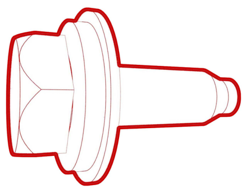
- Install the insulator for the DC input assembly.
.png)
- Fasten the clips that attach the HV battery AC inlet harness cover to the power conversion system.
.png)
- Connect the HV battery AC inlet harness to the power conversion system connector.
.png)
- Connect the electrical harness to the HV battery fast charge contactor connector.
.png)
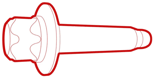
- Install the HV battery probing guide into the penthouse, and then fasten the clips that attach the guide to the HV battery.
.png)
- Install the clip that attaches the HV battery penthouse harness to the HV battery fast charge contactor.
- Install the power conversion system coolant output tube. See Tube - Output - Coolant - Power Conversion System (Remove and Replace).
Caution:
Make sure that the coolant output tube is securely connected by firmly pressing down on the fittings, verify that both clips have fully engaged the barb on the power conversion system and battery flange, and then pull up on the fittings to check retention.
- Perform a penthouse coolant leak test. See Penthouse Coolant Leak Test.
- Connect the 12V auxiliary battery negative terminal only.
.png) Torque 6 Nm
Torque 6 Nm
Caution:
Do not follow the procedure to connect 12V power at this time.
- Connect a 12V charger to the 12V auxiliary battery terminals.
- Refill the coolant. See Penthouse Coolant (Drain and Refill).
- On the touchscreen, touch Controls > Safety & Security > Vehicle Power > Power Off.
- Disconnect the 12V charger from the 12V auxiliary battery terminals.
- Disconnect the 12V auxiliary battery negative terminal.
- Install the HV battery negative contactor. See Contactor - Negative - HV Battery (Remove and Replace)
READ NEXT:
 Contactor - Negative - HV Battery- Remove
SPECIAL TOOLS
Ratchet, 1/4" Sq Dr, HV Insulated (1057602-00-A)
Ext Bar, Wobble, 1/4" Dr, HV Insulated (1057603-00-A)
Magnet, Flexible, HV Insulated, 18" (1057607-00-A)
Socket, 1/4" Dr, Deep,10 mm,Th
Contactor - Negative - HV Battery- Install
Install
Use an IPA wipe to clean the high voltage mating surfaces of the HV
battery terminal, negative busbar, and the HV battery negative contactor.
Install the HV battery negative contac
SEE MORE:
About the Security System
If Model 3 does not detect an authenticated
phone, key fob, or key card and a locked door
or trunk is opened, an alarm sounds and the
headlights and turn signals flash. To deactivate
the alarm, press any button on the mobile app
or tap your key card or key fob against the
card reader located j
Damper - Rear - LH (Coil Suspension) (Remove and Replace)
Remove
Raise and support the vehicle on a 2 post lift. See
Raise Vehicle - 2 Post Lift.
Remove the LH rear wheel. See Wheel (Remove and
Install).
