Tesla Model 3: Controller - High Voltage- Install
Tesla Model 3 2017-2024 Service Manual / Battery System / HV Battery Electrical Components / Controller - High Voltage (Remove and Replace) / Controller - High Voltage- Install
Install
- If a new 4-bolt high voltage controller is replacing an old 5-bolt high voltage controller, perform these additional steps to retrofit a 28-bolt penthouse cover with an aluminum retrofit patch. Otherwise go to step 5.
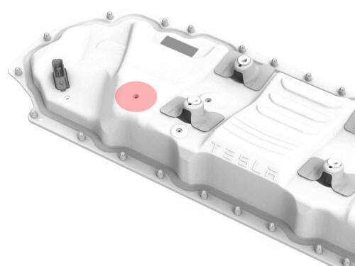
- Use an IPA wipe to clean the area around the high voltage controller middle bolt hole on the outside of the penthouse cover, and allow it to completely dry.
.jpg)
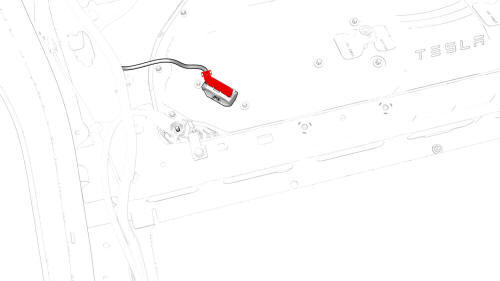
- Cut a 50mm x 50mm patch of aluminum tape, and apply the patch to the outside of the penthouse cover, centered over the middle bolt hole.
- Use a silicon roller to wet out the patch and set the adhesive.
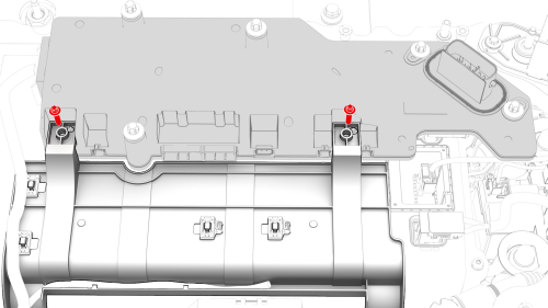
- Install the high voltage controller into the penthouse, and then install
the bolts that attach the high voltage controller to the hinge tray.
 Torque 2 Nm
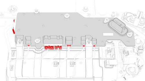
- Connect the penthouse harness to the high voltage controller connectors.
- Install the pyrotechnic battery disconnect into the penthouse. See Pyrotechnic Battery Disconnect (Remove and Replace).
- Use an IPA wipe to clean any residue from the high voltage controller mounting bolt holes and both the inside and outside of the penthouse cover at the bolt holes.
- Use IPA wipes to clean the mating surface of the HV battery and the penthouse cover gasket.
.jpg)
- Install the penthouse cover on the HV battery, and then hand-tighten the bolts.
Note: Different penthouse cover revisions have 28, 18, or 16 bolts.
.png) 28-Bolt Penthouse Cover Torque Sequence
28-Bolt Penthouse Cover Torque Sequence
.jpg) 18-Bolt Penthouse Cover Torque Sequence
18-Bolt Penthouse Cover Torque Sequence
- Torque the penthouse cover bolts in the sequence shown, and mark each
with a green paint pen as they are torqued.
.jpg) Torque 8 Nm
Torque 8 Nm
.jpg) 16-Bolt Penthouse Cover Torque Sequence
16-Bolt Penthouse Cover Torque Sequence
.png)
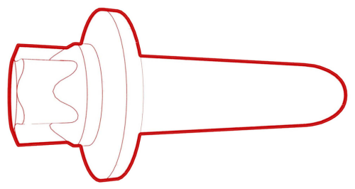
- Connect the positive 12V output cable to the DCDC passthrough, install a
new nut to attach the cable, and mark the nut with a green paint pen after
torque.
.jpg) Torque 9 Nm
Torque 9 Nm
Caution: Make sure that the rubber boot is not trapped under the cable lug or pinched between the cable lug and nut.
- Replace the cover on the positive 12V output cable at the DCDC passthrough, and then press down to attach the cover.
- If the high voltage controller being installed was removed earlier, go to step 30. Otherwise, continue to the next step.
- Connect the electrical harness to the high voltage controller connector.
Note: Make sure not to pull up on the high voltage controller connector when connecting the electrical harness or anytime during in the following steps, as this might close the HVIL loop, close the contactors, and cause the high voltage controller restore to fail.
- Attach a 12V charger to the 12V auxiliary battery positive terminal and the 12V auxiliary battery negative cable.
- Attach the laptop with toolbox to the vehicle.
- In Toolbox, click Autodiag, and type "restore" into the search field.
- Click the arrow next to "HVBMS clone restore", and then click Run Network.
Note: Enter the ID number that was recorded earlier.
- In Toolbox, click Action, and then type "service-redeploy" into the search field.
- Click the arrow next to "UPDATE-SERVICE-REDEPLOY", and then click Run.
- In Toolbox, click Autodiag, and type "restore" into the search field.
- Click the arrow next to "HVP clone restore", and then click Run Network.
Note: Enter the ID number that was recorded earlier.
- In Toolbox, click Action, and then type "service-redeploy" into the search field.
- Click the arrow next to "UPDATE-SERVICE-REDEPLOY", and then click Run.
- When the redeploy finishes, perform any firmware updates.
- Disconnect the laptop from the vehicle.
- Disconnect the 12V charger from the 12V auxiliary battery positive terminal and the 12V auxiliary battery negative cable.
- Disconnect the electrical harness from the high voltage controller connector.
- Continue the procedure to install the penthouse cover. See Cover - Penthouse (Remove and Replace).
READ NEXT:
 DC Input Assembly - HV Battery- Remove
SPECIAL TOOLS
Ratchet, 1/4" Sq Dr, HV Insulated (1057602-00-A)
Skt, 1/4" Sq Dr, 13mm, HV Insulated (1057606-00-A)
Magnet, Flexible, HV Insulated, 18" (1057607-00-A)
Skt, 1/4in Dr, 5-Lobe Torx Plus Ext
DC Input Assembly - HV Battery- Install
Install
Install the DC input assembly to the penthouse, install the bolts (x4)
that attach the DC input assembly to the penthouse, and then mark the bolts
with a paint pen after they are torqu
SEE MORE:
Deadfronts - Pin - Charge Port (NA) (Remove and Replace)
SPECIAL TOOLS
Cap, Logic Conn, Inv, 3DU (1108272-00-B)
Test Probes, Slim, Fluke TP38 (1130480-00-A)
Warning:
Wheel Arch Liner - Front - LH (Remove and Replace)
SPECIAL TOOLS
Pliers, Clip Removal (1133569-00-A)
Remove
Remove the LH front wheel. See
Wheel (Remove and Install).
Remove the bolt and release the clips (x18) that attach the LH front
wheel arch liner to the vehicle, and then remove the liner from the vehicle.
Torque 5 Nm
© 2019-2024 Copyright www.tmodel3.com
