Tesla Model 3: DC Input Assembly - HV Battery (Remove and Replace)
SPECIAL TOOLS Ratchet, 1/4" Sq Dr, HV Insulated (1057602-00-A) Skt, 1/4" Sq Dr, 13mm, HV Insulated (1057606-00-A) Magnet, Flexible, HV Insulated, 18" (1057607-00-A) Skt, 1/4in Dr, 5-Lobe Torx Plus External (1059330-00-B) Resistance meter, microohm, Hioki RM 3548 (1076927-00-A) Warning: Only technicians who have been trained in High
Voltage Awareness are permitted to perform this procedure. Proper personal
protective equipment (PPE) and insulating HV gloves with a minimum rating of
class 0 (1000V) must be worn at all times a high voltage cable, busbar, or
fitting is handled. Refer to Tech Note TN-15-92-003, "High Voltage Awareness
Care Points" for additional safety information. Remove
Install
Note: The maximum acceptable resistance is 0.060 mΩ (60 μΩ). If the
resistance is above this value, escalate a Toolbox session, as appropriate.
Note: The maximum acceptable resistance is 0.060 mΩ (60 μΩ). If the
resistance is above this value, escalate a Toolbox session, as appropriate.
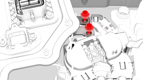
DC Input Assembly - HV Battery- Remove
.png)
.jpg)
.png)
DC Input Assembly - HV Battery- Install
.png) Torque 6 Nm
Torque 6 Nm
.png) Torque 9 Nm
Torque 9 Nm.jpg) Generic Measurement - Actual busbars and fasteners might appear
different
Generic Measurement - Actual busbars and fasteners might appear
different
Generic Measurement - Actual busbars and fasteners might appear
different
.png)
READ NEXT:
 Fuse - A/C Compressor - HV Battery (Remove and Replace)
Fuse - A/C Compressor - HV Battery- Remove
SPECIAL TOOLS
Ratchet, 1/4" Sq Dr, HV Insulated (1057602-00-A)
Ext Bar, Wobble, 1/4" Dr, HV Insulated (1057603-00-A)
Skt, 1/4" Sq Dr, 8mm, HV Insulated (10
SEE MORE:
SIM Card - Car Computer (Remove and Replace)
DRAFT
Warning:
This procedure was derived from pre-production computer models, and
might not reflect the real-world situation. Warnings and cautions might be
missing. Follow safety requirements and use extreme caution when working on or
near high voltage systems and components.
Remove
Remove
Disclaimers
Event Data Recorder (EDR)
Model 3 is equipped with an event data
recorder (EDR). The main purpose of an EDR
is to record, in certain crash or near crash-like
situations, such as an air bag deployment or
hitting a road obstacle, data that will assist in
understanding how a vehicle's systems
