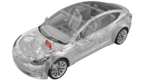
Tesla Model 3: Module - Body Controller - Front (Dual Motor) (Remove and Replace)
Module - Body Controller - Front (Dual Motor) - Remove
Remove
- Remove the 2nd row lower seat cushion. See Seat Cushion - Lower - 2nd
Row (Remove and Replace).
- Remove the rear underhood apron. See Underhood Apron - Rear (Remove and
Replace).
- Remove the cabin intake duct. See Duct - Cabin Intake (Remove and
Replace).
- Remove the underhood storage unit. See Underhood Storage Unit (Remove
and Replace).
- Remove the LH and RH wiper arms. See Wiper Arms (Remove and Replace).
- Remove the LH and RH shock tower covers. See Cover - Shock Tower - LH (Remove
and Replace).
- Remove the cowl screen panel. See Panel - Cowl Screen (Remove and
Replace).
- Disconnect 12V power. See 12V Power (Disconnect and Connect).
- Remove the 12V auxiliary battery. See Battery - 12V (Remove and Replace).
.png)
- Remove the bolt that attaches the 12V battery rear hook tie down to the
body, and then remove the tie down from the body.
.png)
- Remove the nuts (x2) that attach the superbottle to the thermal beam.
.jpg)
- Remove the upper bolts (x2) that attach the battery bracket to the
vehicle.
.png)
- Release the clip that attaches the coolant hose to the 12V battery
bracket.
.jpg)
- Release the clip that attaches the 12V battery vent hose to the 12V
battery bracket.
.jpg)
- Loosen the inner bolts that attach the shock tower brace to the RH shock
tower.
.jpg)
- Loosen the outer bolt that attaches the shock tower brace to the RH
shock tower.
.jpg)
- Remove the inner bolts that attach the shock tower brace to the LH shock
tower.
.jpg)
- Remove the outer bolt that attaches the shock tower brace to the LH
shock tower.
- Shift the LH side of the shock tower brace towards the front of the
vehicle to increase working space.
.png)
- Remove the bolt that attaches the thermal harness cover to the front
body controller module, and then remove the cover from the module.
.png)
- Disconnect the thermal harness from the front body controller module
connector.
.png)
- Release the clip that attaches the suction/liquid lines to the body near
the TXV, and then move the electrical harness aside to gain access to the
front body controller module.
.png)
- Remove the bolts (x9) that attach the front body controller module cover
to the front body controller module, and then remove the cover.
.jpg)
- Disconnect the electrical harness from the front body controller module
connectors (x4).
.jpg)
- Remove and discard the nuts (x6) and bolt that attach the power and
ground cables to the front body controller module.
.jpg)
- Remove the bolts (x3) that attach the front body controller module to
the body.
.png)
- Release the clips (x2) that attach the bottom of the front body
controller module to the body, and then remove the lower busbar from the
stud.
.png)
- Remove the bolt that attaches the ground strap to the upper rear of the
front body controller module, and then remove the ground strap from the
module.
.png)
- Remove the bolt that attaches the ground strap to the lower right side
of the front body controller module, and then remove the ground strap from
the module.
.png)
- Remove the bolt that attaches the ground strap to the lower rear of the
front body controller module, and then remove the ground strap from the
module.
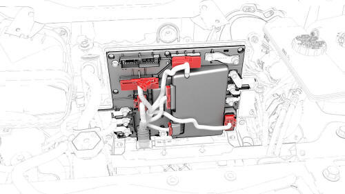
- Remove the front body controller module from the vehicle.
Module - Body Controller - Front (Dual Motor) - Install
Install
- Set the front body controller module where it installs into the vehicle,
and then tilt the module forward
- Install the ground strap to the lower rear of the front body controller
module, and then install the bolt that attaches the ground strap to the
module.
.png) Torque 9 Nm
Torque 9 Nm
- Install the ground strap to the lower right side of the front body
controller module, and then install the bolt that attaches the ground strap
to the module.
Torque 9 Nm
- Install the ground strap to the upper rear of the front body controller
module, and then install the bolt that attaches the ground strap to the
module.
Torque 9 Nm
- Slide the busbar onto the lower stud, and then fasten the electrical
harness clips (x2) to the bottom of the front body controller module.
- Install the bolts (x3) that attach the front body controller module to
the body.
.jpg) Torque 10 Nm
Torque 10 Nm
.jpg) Torque 10 Nm
Torque 10 Nm
- Install new nuts (x6) and new bolt to attach the power and ground cables
to the front body controller module.
.jpg) Torque 8.5 Nm
Torque 8.5 Nm
.jpg) Torque 8.5 Nm
Torque 8.5 Nm
Note: Make sure that the terminal lugs fit in their channels neatly.
- Connect the electrical harness to the front body controller module
connectors (x4).
.jpg)
- Visually inspect that the power and the ground cables exit the front
body controller module neatly in their respective channels, and parallel to
each other.
Caution: Make sure that no cables or wires will be pinched when
the front body controller module cover is installed.
.jpg)
- Install the front body controller module cover to the front body
controller module, and then install the bolts (x9) that attach the cover to
the module.
.png) Torque 6 Nm
Torque 6 Nm
- Connect the thermal harness to the front body controller module
connector.
- Fasten the clip that attaches the suction/liquid lines to the body near
the TXV.
- Install the thermal harness cover to the front body controller module,
and then install the bolt that attaches the cover to the module.
.png) Torque 6 Nm
Torque 6 Nm
- Shift the LH side of the shock tower brace rearward so that the bolt
holes in the brace and shock tower align.
- Install the outer bolt that attaches the shock tower brace to the LH
shock tower.
.jpg) Torque 62 Nm
Torque 62 Nm
- Install the inner bolts (x2) that attach the shock tower brace to the LH
shock tower.
.jpg) Torque 67 Nm
Torque 67 Nm
.jpg) Torque 67 Nm
Torque 67 Nm
- Tighten the outer bolt that attaches the shock tower brace to the RH
shock tower.
Torque 62 Nm
- Tighten the inner bolts (x2) that attach the shock tower brace to the RH
shock tower.
Torque 67 Nm
Torque 67 Nm
- Fasten the clip that attaches the 12V battery vent hose to the 12V
battery bracket.
- Fasten the clip that attaches the coolant hose to the 12V battery
bracket.
- Install the upper bolts (x2) that attach the battery bracket to the
vehicle.
.jpg) Torque 15 Nm
Torque 15 Nm
- Install the nuts (x2) that attach the superbottle to the thermal beam.
.png) Torque 8 Nm
Torque 8 Nm
- Install the 12V battery rear hook tie down to the body, and then install
the bolt that attaches the tie down to the body.
.png) Torque 9 Nm
Torque 9 Nm
- Install the 12V auxiliary battery. See Battery - 12V (Remove and Replace).
- Connect 12V power. See 12V Power (Disconnect and Connect).
- Connect a laptop with Toolbox to the vehicle.
- Use Toolbox to update the vehicle firmware.
- In Toolbox, click the play button next to the "TESTRESET_ VCFRONT" and
select Run,
- Disconnect the laptop from the vehicle.
- Install the cowl screen panel. See Panel - Cowl Screen (Remove and
Replace).
- Install the LH and RH shock tower covers. See Cover - Shock Tower - LH (Remove
and Replace).
- Install the LH and RH wiper arms. See Wiper Arms (Remove and Replace).
- Install the underhood storage unit. See Underhood Storage Unit (Remove
and Replace).
- Install the cabin intake duct. See Duct - Cabin Intake (Remove and
Replace).
- Install the rear underhood apron. See Underhood Apron - Rear (Remove and
Replace).
- Install the 2nd row lower seat cushion. See Seat Cushion - Lower - 2nd
Row (Remove and Replace).
READ NEXT:
Module - Body Controller - Front (RWD) - Remove
Remove
Remove the 2nd row lower seat cushion. See
Seat Cushion - Lower - 2nd Row (Remove and Replace).
Remove the rear underhood apron. See
Under
SEE MORE:
Fuse - Cabin Heater - HV Battery- Remove
SPECIAL TOOLS
Ratchet, 1/4" Sq Dr, HV Insulated (1057602-00-A)
Ext Bar, Wobble, 1/4" Dr, HV Insulated (1057603-00-A)
Skt, 1/4" Sq Dr, 8mm, HV Insulated (1057604-00-A)
Magnet, Flexible, HV Insulated, 18" (1057607-00-A)
Asy, Service Cover, Penthouse, Model 3
Steering Column - Remove
Note:
This procedure was formulated using a release candidate or
production model. Follow safety requirements and use extreme
caution when working on or near high-voltage systems and
com
 Module - Body Controller - Front (RWD) (Remove and Replace)
