Tesla Model 3: Inverter - Rear Drive Unit (Remove and Install)
SPECIAL TOOLS
Skt, 3/8in Dr, 10EP Torx Plus External (1130479-00-A)
Remove Install
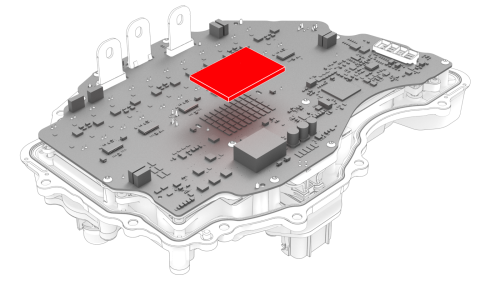
Caution:
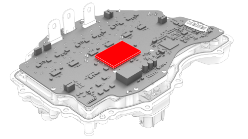
Avoid damage to the printed circuit board of the
inverter.
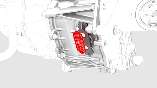
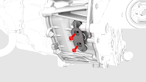
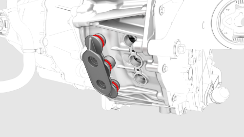
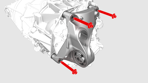
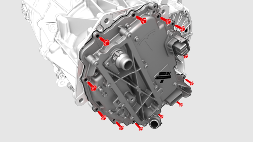
Inverter - Rear Drive Unit - Remove
.jpg)
Inverter - Rear Drive Unit - Install
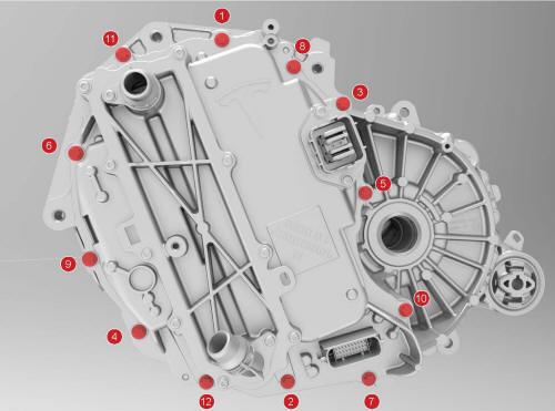
 Torque 5 Nm +20 deg
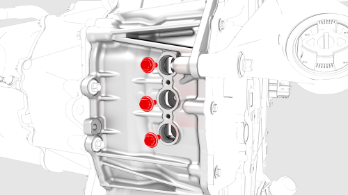
.png) Torque 35 Nm +55 deg
Torque 35 Nm +55 deg
 Torque 11.5 Nm
.png) Torque 5 Nm +40 deg
Torque 5 Nm +40 deg
 Torque 7.5 Nm
READ NEXT:
 Inverter - Rear Drive Unit (Remove and
Replace)
Inverter - Rear Drive Unit (Remove and
Replace)
Inverter - Rear Drive Unit - Remove
SPECIAL TOOLS
Skt, 3/8in Dr, 10EP Torx Plus External
(1130479-00-A)
SEE MORE:
HV Battery Air Leak Test
Pack Enclosure Leak Tester, HV Battery (1026636-00-A)
Pack Kit, Enclosure, Leak Test, HV Battery, Complete (1140501-00-A)
Kit, Encl Leak Test Adapters, HV Battery (1144879-00-A)
Procedure
Perform the vehicle electrical isolation procedure. See
Vehicle Electrical Isolation Procedure.
Remove the p
Subframe Assembly - Front (RWD) (Remove and Replace)
Caution:
Vehicles built before March 25th, 2019 have 1st generation front
subframes. Vehicles built on March 25th, 2019 and after have 2nd generation
front subframes. When a 1st generation subframe is replaced with a 2nd
generation subframe, the 1st generation (discontinued) steering rack, if
