Tesla Model 3: Inverter - Rear Drive Unit (Remove and Replace)
SPECIAL TOOLS
Skt, 3/8in Dr, 10EP Torx Plus External
(1130479-00-A)
Lever Lock, HV Connector, Model 3 (1140311-00-A)
Remove
Install
Caution:
Avoid damage to the printed circuit board of the
inverter.
Caution:
Make sure that the harness fits the connector
squarely and tightly.
Caution:
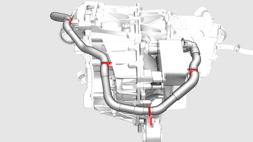
Perform a push-pull test to verify that the hose
is fully seated.
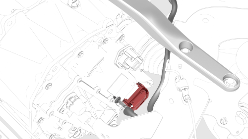
Inverter - Rear Drive Unit - Remove
.jpg)
.png)
.jpg)
.png)
.png)
.png)
.png)
.png)
.png)
.png)
.png)
.jpg)
Inverter - Rear Drive Unit - Install
.png)
.jpg)
.png) Torque 5 Nm +20 deg
Torque 5 Nm +20 deg
.png) Torque 11.5 Nm
Torque 11.5 Nm
.png) Torque 5 Nm +40 deg
Torque 5 Nm +40 deg
.png) Torque 7.5 Nm
Torque 7.5 Nm
.png)
.png) Torque 6 Nm
Torque 6 Nm
READ NEXT:
 Powertrain Coolant (Drain and Refill)
Powertrain Coolant - Drain
SPECIAL TOOLS
Drive Unit Pressure Test Fixture (1053600-00-C)
Kit, Coolant Leak Tes
SEE MORE:
Trim - Floor - Trunk (Remove and Replace)
Remove
Open the rear trunk.
Lift up the trunk floor trim and remove it from the vehicle.
Tip:
Use the pull tab located at the rear edge of the trunk floor trim.
Install
Installation procedure is the reverse of removal.
Drive Unit - Rear (Remove and Replace)
Remove
Remove the rear drive unit from the subframe
assembly. See Drive Unit - Rear (Remove and Install).
