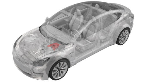
Tesla Model 3: Booster - Brake - Electromechanical (LHD) (Remove and Replace)
SPECIAL TOOLS
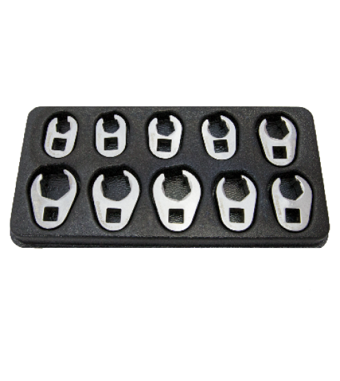
Flare nut crowfoot set (1079041-00-A)
Kit, EPB Release, Handheld (1134520-00-A)
XP-10 Power Supply, XP-10 (1129348-00-A)
Remove
Caution: Brake fluid dissolves paint. Have clean towels and plenty of water standing by to wash spilled brake fluid off painted surfaces.Note: Dispose of used brake fluid in a manner consistent with local environmental codes.
- Raise and support the vehicle. See Raise Vehicle - 2 Post Lift.
.jpg)
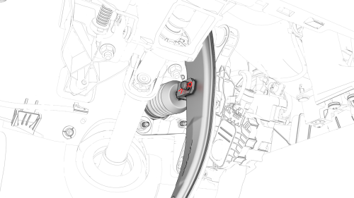
- Disconnect the electrical harness from the LH rear brake caliper connector.
- Connect the Electronic Parking Brake (EPB) release tool to the LH rear brake caliper connector.
- Use the EPB release tool to release the parking brake.
- Disconnect the EPB release tool from the LH rear brake caliper connector.
- Repeat step 2 through step 5 for the RH rear brake caliper.
- Remove the underhood storage unit. See Underhood Storage Unit (Remove and Replace).
- Disconnect 12V power. See 12V Power (Disconnect and Connect).
- Remove the wiper motor. See Wiper Motor (Remove and Replace).
- Remove the front body controller module. See Module - Body Controller - Front (RWD) (Remove and Replace).
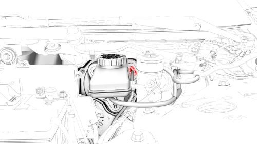
- Disconnect the electrical harness from the brake fluid reservoir connector.
- Disconnect the electrical harness from the electromechanical brake booster connector.
- Place absorbent material under the reservoir and booster.
- Remove fluid from the reservoir.
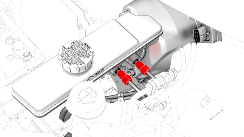
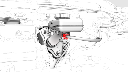
- Loosen the nuts that attach the brake lines to the
booster, and then slide the nuts back on the brake
lines.
 Torque 16 Nm
- Remove the driver knee airbag. See Airbag - Knee - Driver (Remove and Install).
- Remove the brake switch. See Switch - Brake Light (Remove and Replace).
- Release the clip from the clevis pin, and then remove the clevis pin from the brake pedal arm.
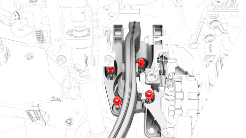
- Remove and discard the nuts that attach the brake
booster to the bulkhead, and then remove the brake
booster from the vehicle.
 Torque 16.5 Nm
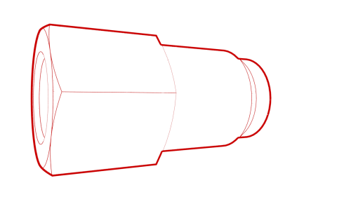
Caution:
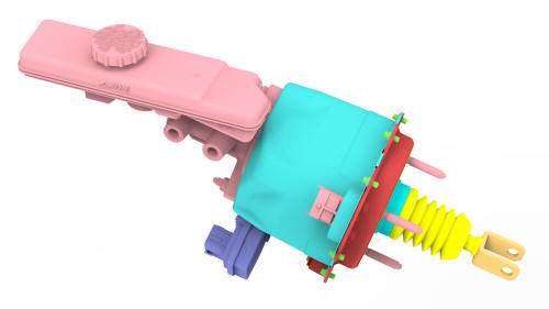
Handle the electromechanical brake booster only
by the main housing. Do not use the pushrod, the
reservoir, or the connectors to lift or
manipulate the electromechanical brake booster.
Install
Installation procedure is the reverse of removal, except for the following:Warning: Do not operate the vehicle until the installation is complete, the braking system has been bled, and you are instructed.
Caution: Handle the electromechanical brake booster only by the main housing. Do not use the pushrod, the reservoir, or the connectors to lift or manipulate the electromechanical brake booster.
Caution: Replace all nyloc nuts.
- Fill the brake fluid reservoir.
- Use Toolbox to update the firmware and verify the operation of the electromechanical brake booster.
- Bleed the braking system. See Brake Fluid Bleed / Flush.
READ NEXT:
 Master Cylinder and Reservoir Assembly (Remove and Replace)
Master Cylinder and Reservoir Assembly - Remove
SPECIAL TOOLS
Flare nut crowfo
SEE MORE:
Puddle Light - Front Door - LH (Remove and Replace)
Remove
Use a small screwdriver or pry tool in the slot at the front of the
puddle light to pry the light out of the bottom of the front LH door trim
panel.
Release the clips that attach the front of the puddle light to the
bottom of the door trim panel, and then separate the light f
Module - Steering Column Control (Remove and Replace)
Module - Steering Column Control - Remove
Remove
Remove the 2nd row lower seat cushion. See Seat
Cushion - Lower - 2nd Row (Remove and Replace).
Remove the rear underhood apron. See Underhood Apron
- Rear (Remo
