Tesla Model 3: Carrier Assembly - Charge Port - Install
Install
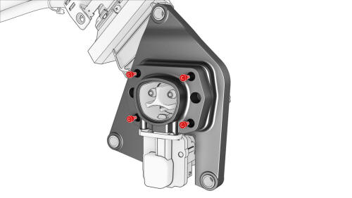
- Position the new carrier assembly on the charge port
assembly, and then install the bolts that attach the
carrier assembly to the charge port assembly.
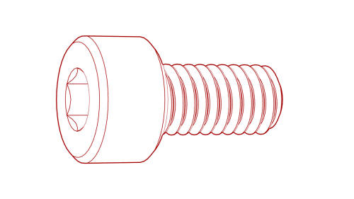 Torque 2.3 Nm
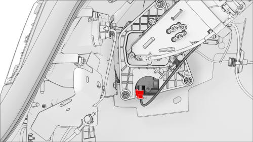
- Connect the electrical connector to the latch actuator.
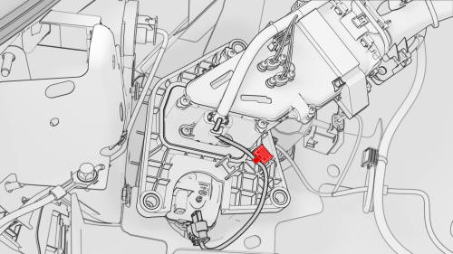
- Position the actuator harness on the carrier assembly as pictured, and then tighten the cable tie around the harness at the same location as the old clip.
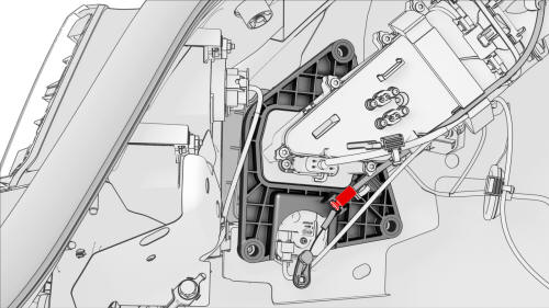
- Install the latch cable to the locking tabs on the carrier assembly.
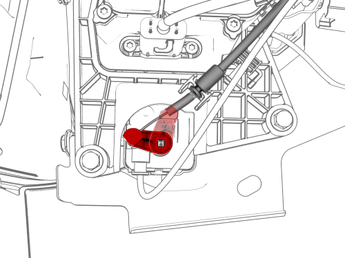
- Install the release arm onto the latch actuator in the same position as when it was removed.
Note: After installation, manually rotate the release arm and check that the latch actuator moves.
Caution: Ensure the latch actuator is oriented correctly, as shown below. Incorrect installation can result in inability to properly latch.
- Position the charge port assembly on the body.
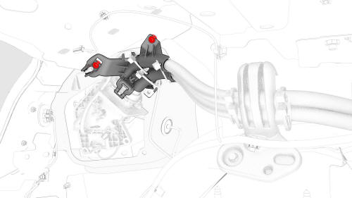
- Install the clips that attach the charge port electrical harness to the body.
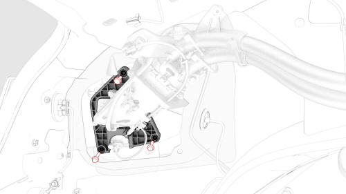
- Install the bolts that attach the charge port
assembly to the body.
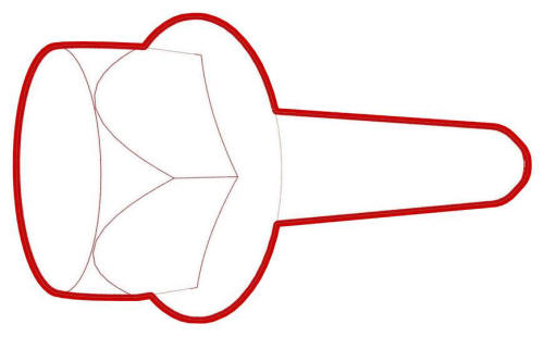 Torque 6 Nm
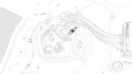
- Install the bolt that attaches the charge port
electrical ground to the body.
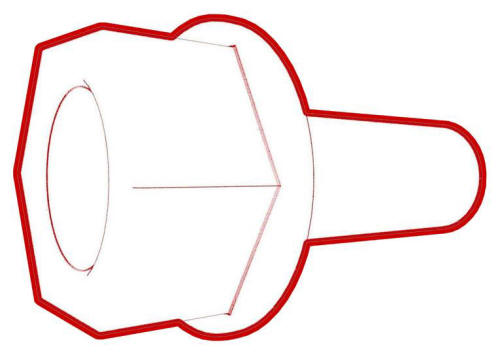 Torque 6 Nm
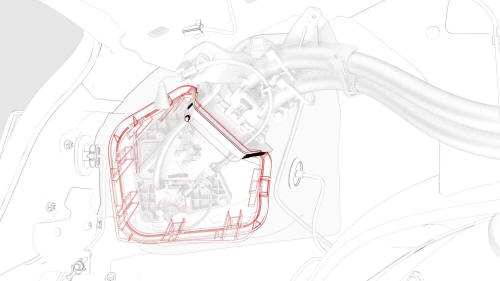
- Align the tabs around the charge port closeout panel, and then install the panel on the vehicle
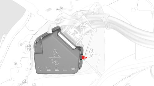
- Install the clip that attaches the low voltage electrical harness to the charge port closeout panel.
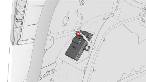
- Connect the low voltage charge port connector to the charge port ECU.
- Install the LH trunk side trim. See Trim - Side - Trunk - LH (Remove and Replace).
- Install the LH rear sill panel trim. See Trim - Sill Panel - Rear - LH (Remove and Replace).
- Reconnect 12V power. See 12V Power (Disconnect and Connect).
- Install the 2nd row lower seat cushion. See Seat Cushion - Lower - 2nd Row (Remove and Replace).
- Open the charge port door, and then plug an unpowered mobile connector into the charge port.
Caution: Do not plug any powered charge cable into the charge port at this time.
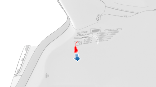
Charge cable manual release
- Verify latch functionality by pulling on the charge cable manual release while simultaneously pulling the mobile connector out of the charge port.
- Verify that the vehicle charges normally.
- Install the rear underhood apron. See Underhood Apron - Rear (Remove and Replace).

