Tesla Model 3: Charge Port Voltage Check
SPECIAL TOOLS
Insulation Multimeter, Fluke 1507 (NA)
(1076921-00-B)
Insulation Multimeter, Fluke 1587 (EMEA)
(1076921-00-A)
Insulation Multimeter, Fluke 1508 (APAC)
(1076921-01-B)
Test Probes, Slim, Fluke TP38 (1130480-00-A)
Warning:
Remove all jewelry (watches, bracelets, rings, necklaces,
earrings, ID tags, piercings, etc.) from your person, and
all objects (keys, coins, pens, pencils, tools, fasteners,
etc.) from your pockets before performing any procedure that
exposes you to high voltage. Warning:
If corrective eyewear is necessary to safely perform any
procedure, make sure that the eyewear is securely restrained
to the head and cannot fall off. Warning:
Only technicians who have been trained in High
Voltage Awareness are permitted to perform this
procedure. Proper personal protective equipment (PPE)
and insulating HV gloves with a minimum rating of
class 0 (1000V) must be worn at all times a high
voltage cable, busbar, or fitting is handled. Refer to Tech
Note TN-15-92-003, "High Voltage Awareness Care Points" for
additional safety information. Warning:
Make sure that the insulation meter and leads are capable of
handling at least 500V DC.
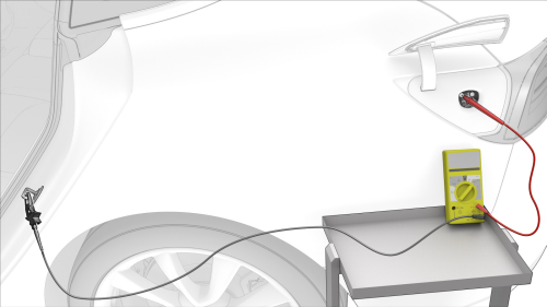
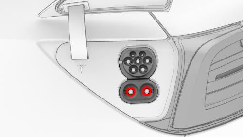
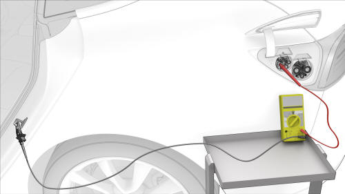
Procedure (Single-Phase)
Warning: If the voltage reading is greater than 10V, the HV battery contactors are closed or welded. Stop
this procedure and escalate a Toolbox session,
as appropriate.
Warning: If the voltage reading is greater than 10V, the HV battery contactors are closed or welded. Stop
this procedure and escalate a Toolbox session,
as appropriate.
Warning:
If the voltage reading is greater than 10V, the HV battery contactors are closed or welded. Stop
this procedure and escalate a Toolbox session,
as appropriate.
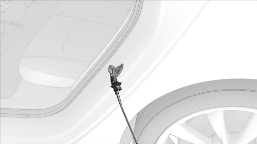
Caution:
If the voltage across the 12V auxiliary battery
terminals is less than 10 volts or greater than
14 volts, the multimeter is not measuring
reliably and must not be used. Use only a fully
functional multimeter.
Caution: If the voltage across the 12V auxiliary battery
terminals is less than 10 volts or greater than
14 volts, the multimeter is not measuring
reliably and must not be used. Use only a fully
functional multimeter.
Procedure (Single - Phase)

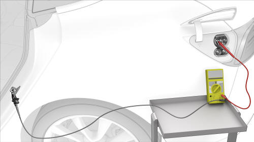
Procedure (Three-Phase) (Except China)
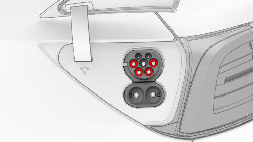
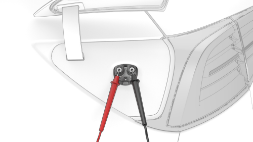
Note: Touch the sides of the terminals inside of
the pin terminals, not the tips.
Note: Touch the sides of the terminals inside of
the pin terminals, not the tips.
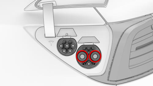
Procedure (Three - Phase) (China)
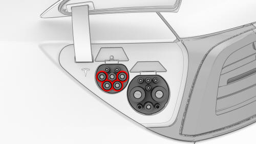
Note: Touch the sides of the terminals inside of
the pin terminals, not the tips.
Note: Touch the sides of the terminals inside of
the pin terminals, not the tips.
READ NEXT:
SEE MORE:
 Light - Fog - Front (Adjust)
Procedure
Special tools required for this procedure:
SPECIAL TOOLS
Pliers, Clip Removal (1133569-00-A)
On a wall, measure 14.5 in (36.8 cm) from the floor, and then apply a
length of 1-inch masking tape horizontally to the wall to mark the
measurement.
Measure 25 ft (7.62 m) from the wall,
Speaker - Front Door - LH (Remove and Replace)
Remove
Remove the LH front door trim panel. See Panel - Door Trim - Front - LH
(Remove and Replace).
Disconnect the electrical connector from the front door speaker.
Remove the screws that attach the front door speaker to the door, and
then remove the speaker.
Torque 4 Nm
In
