Tesla Model 3: Contactor - Positive - HV Battery-Install
Tesla Model 3 2017-2024 Service Manual / Battery System / HV Battery Electrical Components / Contactor - Positive - HV Battery (Remove and Replace) / Contactor - Positive - HV Battery-Install
Install
Caution:
- Replace all patchbolts.
- Replace all nyloc nuts.
- Use an IPA wipe to clean the high voltage mating surfaces of the HV battery terminal, positive busbar, and the HV battery positive contactor.
- Tilt the rear of the HV battery positive contactor up, and then install the contactor into the penthouse.
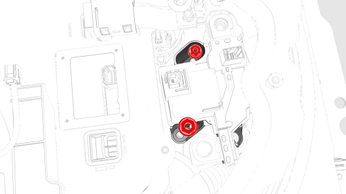
- Install the nuts (x3) that attach the HV battery positive contactor into
the penthouse.
 Torque 8 Nm
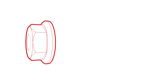
- Install a new nut to attach the HV battery positive contactor onto the
HV battery terminal, and then mark the nut with a paint pen after it is
torqued.
 Torque 9 Nm
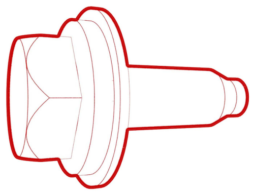
.jpg) Generic Measurement - Actual busbars and fasteners might appear
different
Generic Measurement - Actual busbars and fasteners might appear
different
- Use the Hioki resistance meter to measure the resistance at the HV joint between the HV battery positive contactor and the HV battery terminal.
Note: The maximum acceptable resistance is 0.110 mΩ (110 μΩ). If the resistance is above this value, escalate a Toolbox session, as appropriate.
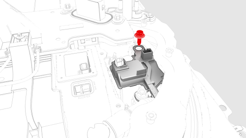
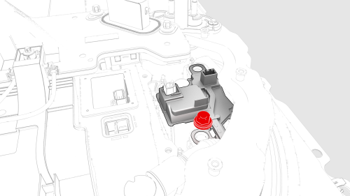
- Install a new bolt to attach the HV battery positive contactor onto the
positive busbar, and then mark the bolt with a paint pen after it is torqued.
 Torque 9 Nm
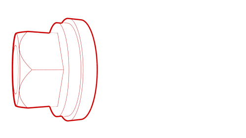
Generic Measurement - Actual busbars and fasteners might appear
different
- Use the Hioki resistance meter to measure the resistance at the HV joint between the HV battery positive contactor and the positive busbar.
Note: The maximum acceptable resistance is 0.060 mΩ (60 μΩ). If the resistance is above this value, escalate a Toolbox session, as appropriate.
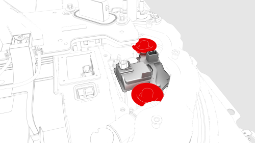
- Install the insulator caps to the HV battery positive contactor.
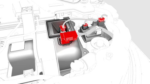
- Connect the electrical harness to the HV battery positive contactor, and power conversion system LV and DC bus HV connectors.
- Install the 12V DCDC passthrough. See Passthrough - DCDC - 12V (Remove and Replace).
- Install the high voltage controller. See Controller - High Voltage (Remove and Replace).
- Install the pyrotechnic battery disconnect into the penthouse. See Pyrotechnic Battery Disconnect (Remove and Replace).
READ NEXT:
 Controller - High Voltage- Remove
Warning: Only technicians who have been trained in High Voltage
Awareness are permitted to perform this procedure. Proper personal protective
equipment (PPE) and insulating HV gloves with a minimu
Controller - High Voltage- Install
Install
If a new 4-bolt high voltage controller is replacing an old 5-bolt high
voltage controller, perform these additional steps to retrofit a 28-bolt
penthouse cover with an aluminum retrofit
SEE MORE:
Link - Fore - Lower - Rear - LH - Remove
SPECIAL TOOLS
Tool, Spring Compressor, Hook, Model 3
(1135103-00-A)
Remove
Raise and support the vehicle. See Raise Vehicle - 2
Post Lift.
Remove the LH rear wheel. See Wheel (Rem
Visual and Audio Feedback
When you shift to Reverse, the Park Assist
view displays on the touchscreen, showing
objects that are in close proximity to the front
and rear of Model 3. This view closes when
you shift into Drive unless an object is
detected close to the front of Model 3, in
which case the Park Assist view c
© 2019-2024 Copyright www.tmodel3.com
