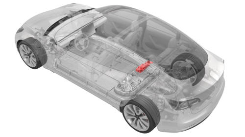
Tesla Model 3: Controller - High Voltage (Remove and Replace)
Controller - High Voltage- Remove
Warning: Only technicians who have been trained in High Voltage
Awareness are permitted to perform this procedure. Proper personal protective
equipment (PPE) and insulating HV gloves with a minimum rating of class 0
(1000V) must be worn at all times a high voltage cable, busbar, or fitting is
handled. Refer to Tech Note TN-15-92-003, "High Voltage Awareness Care Points"
for additional safety information.
- Perform the vehicle isolation procedure. See
Vehicle Electrical Isolation Procedure.
- If the high voltage controller is being removed as part of another
component's replacement procedure, and the same controller will be installed
later, go to step
14. Otherwise, continue to the next step.
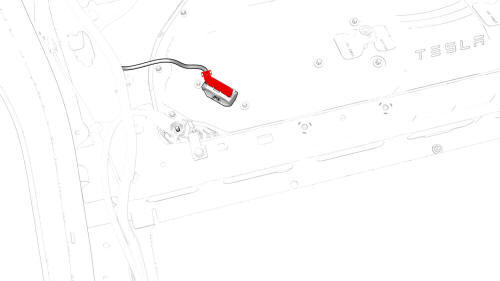
- Remove the RH inner 2nd row rail. See
Rail - 2nd Row - Inner - LH (Remove and Replace).
.jpg) 28-Bolt Penthouse Cover
28-Bolt Penthouse Cover
.jpg) Retrofit Patch, 18-Bolt, and 16-Bolt Penthouse Covers
Retrofit Patch, 18-Bolt, and 16-Bolt Penthouse Covers
- Remove and discard the bolts that attach the high voltage controller
internally to the penthouse cover.
- Connect the electrical harness to the high voltage controller connector.
Note: Make sure not to pull up on the high voltage controller
connector when connecting the electrical harness or anytime during in the
following steps, as this might close the HVIL loop, close the contactors, and
cause the high voltage controller backup to fail.
- Attach a 12V charger to the 12V auxiliary battery positive terminal and
the 12V auxiliary battery negative cable.
- Attach the laptop with toolbox to the vehicle.
- Verify that the firmware version is 2019.12.1 or later, and update if
necessary.
- In Toolbox, click Autodiag, and type "backup" into the search field.
- Click the arrow next to "HVC clone backup", and then click Run Network.
- Record the ID number that is displayed in the Autodiag.
- When the Autodiag finishes, disconnect the 12V charger from the 12V
auxiliary battery positive terminal and the 12V auxiliary battery negative
cable.
- Disconnect the electrical harness from the high voltage controller
connector.
- Remove the penthouse cover. See
Cover - Penthouse (Remove and Replace).
- Remove the pyrotechnic battery disconnect from the penthouse. See
Pyrotechnic Battery Disconnect (Remove and Replace).
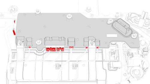
- Disconnect the penthouse harness from the high voltage controller
connectors.
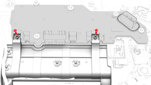
- Remove the bolts that attach the high voltage controller to the hinge
tray, and then remove the controller from the vehicle.
 Torque 2 Nm
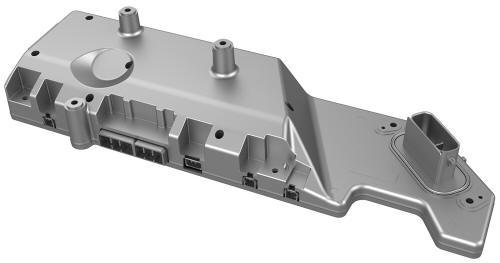 5-Bolt High Voltage Controller
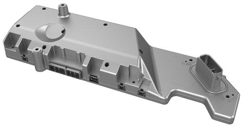 4-Bolt High Voltage Controller
Controller - High Voltage- Install
Install
- If a new 4-bolt high voltage controller is replacing an old 5-bolt high
voltage controller, perform these additional steps to retrofit a 28-bolt
penthouse cover with an aluminum retrofit patch. Otherwise go to step
5.
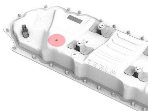
- Use an IPA wipe to clean the area around the high voltage controller
middle bolt hole on the outside of the penthouse cover, and allow it to
completely dry.
.jpg)
- Cut a 50mm x 50mm patch of aluminum tape, and apply the patch to the
outside of the penthouse cover, centered over the middle bolt hole.
- Use a silicon roller to wet out the patch and set the adhesive.
- Install the high voltage controller into the penthouse, and then install
the bolts that attach the high voltage controller to the hinge tray.
Torque 2 Nm
- Connect the penthouse harness to the high voltage controller connectors.
- Install the pyrotechnic battery disconnect into the penthouse. See
Pyrotechnic Battery Disconnect (Remove and Replace).
- Use an IPA wipe to clean any residue from the high voltage controller
mounting bolt holes and both the inside and outside of the penthouse cover
at the bolt holes.
- Use IPA wipes to clean the mating surface of the HV battery and the
penthouse cover gasket.
.jpg)
- Install the penthouse cover on the HV battery, and then hand-tighten the
bolts.
Note: Different penthouse cover revisions have 28, 18, or 16 bolts.
.png) 28-Bolt Penthouse Cover Torque Sequence
28-Bolt Penthouse Cover Torque Sequence
.jpg) 18-Bolt Penthouse Cover Torque Sequence
18-Bolt Penthouse Cover Torque Sequence
- Torque the penthouse cover bolts in the sequence shown, and mark each
with a green paint pen as they are torqued.
.jpg) Torque 8 Nm
Torque 8 Nm
.jpg) 16-Bolt Penthouse Cover Torque Sequence
16-Bolt Penthouse Cover Torque Sequence
.png)
- Connect the positive 12V output cable to the DCDC passthrough, install a
new nut to attach the cable, and mark the nut with a green paint pen after
torque.
.jpg) Torque 9 Nm
Torque 9 Nm
Caution: Make sure that the rubber boot
is not trapped under the cable lug or pinched between the cable lug and nut.
- Replace the cover on the positive 12V output cable at the DCDC
passthrough, and then press down to attach the cover.
- If the high voltage controller being installed was removed earlier, go
to step
30. Otherwise, continue to the next step.
- Connect the electrical harness to the high voltage controller connector.
Note: Make sure not to pull up on the high voltage controller
connector when connecting the electrical harness or anytime during in the
following steps, as this might close the HVIL loop, close the contactors, and
cause the high voltage controller restore to fail.
- Attach a 12V charger to the 12V auxiliary battery positive terminal and
the 12V auxiliary battery negative cable.
- Attach the laptop with toolbox to the vehicle.
- In Toolbox, click Autodiag, and type "restore" into the search field.
- Click the arrow next to "HVBMS clone restore", and then click Run
Network.
Note: Enter the ID number that was recorded earlier.
- In Toolbox, click Action, and then type "service-redeploy" into the
search field.
- Click the arrow next to "UPDATE-SERVICE-REDEPLOY", and then click Run.
- In Toolbox, click Autodiag, and type "restore" into the search field.
- Click the arrow next to "HVP clone restore", and then click Run Network.
Note: Enter the ID number that was recorded earlier.
- In Toolbox, click Action, and then type "service-redeploy" into the
search field.
- Click the arrow next to "UPDATE-SERVICE-REDEPLOY", and then click Run.
- When the redeploy finishes, perform any firmware updates.
- Disconnect the laptop from the vehicle.
- Disconnect the 12V charger from the 12V auxiliary battery positive
terminal and the 12V auxiliary battery negative cable.
- Disconnect the electrical harness from the high voltage controller
connector.
- Continue the procedure to install the penthouse cover. See
Cover - Penthouse (Remove and Replace).
READ NEXT:
DC Input Assembly - HV Battery- Remove
SPECIAL TOOLS
Ratchet, 1/4" Sq Dr, HV Insulated (1057602-00-A)
Skt, 1/4" Sq Dr, 13mm, HV Insulated (1057606-00-A)
Magnet, Flexible, HV Insulated, 18" (1057607-00
SEE MORE:
SPECIAL TOOLS
Camera Calibration Target (1053066-00-A)
Wrench, 2.5mm, Thin (1448868-00-A)
Note: This procedure describes how to calibrate the forward
facing cameras. It does not apply to the rear facing camera.
Setup
Park the vehicle on a flat surface with at least 106 cm (3.5 ft) of
space in
Wipers
To perform a single wipe with the windshield
wipers, press and immediately release the
button on the end of the left-hand steering
column lever.
To adjust the continuous wiper settings, touch
the windshield wiper icon located in the
"Cards" area on the touchscreen. The wipe
 DC Input Assembly - HV Battery (Remove and Replace)
