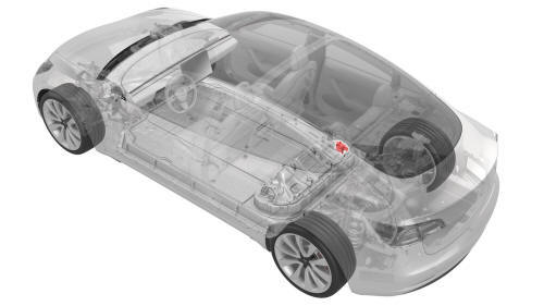
Tesla Model 3: Contactor - Positive - HV Battery (Remove and Replace)
SPECIAL TOOLS Ratchet, 1/4" Sq Dr, HV Insulated (1057602-00-A) Ext Bar, Wobble, 1/4" Dr, HV Insulated (1057603-00-A) Magnet, Flexible, HV Insulated, 18" (1057607-00-A) Socket, 1/4" Dr, Deep,10 mm,Thin Wall, Insul (1133768-00-A) Resistance meter, microohm, Hioki RM 3548 (1076927-00-A) Warning: Only technicians who have been trained in High Voltage Awareness are
permitted to perform this procedure. Proper personal protective equipment (PPE)
and insulating HV gloves with a minimum rating of class 0 (1000V) must be worn
at all times a high voltage cable, busbar, or fitting is handled. Refer to Tech
Note TN-15-92-003, "High Voltage Awareness Care Points" for additional safety
information. Remove
Install Caution:
Note: The maximum acceptable resistance is 0.110 mΩ (110 μΩ). If
the resistance is above this value, escalate a Toolbox session, as appropriate.
Note: The maximum acceptable resistance is 0.060 mΩ (60 μΩ). If the
resistance is above this value, escalate a Toolbox session, as appropriate.
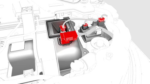
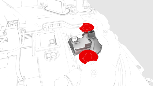
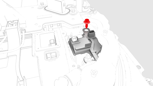
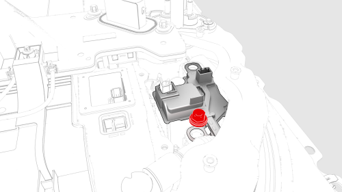
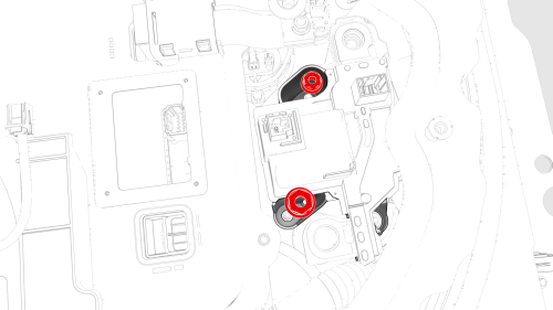
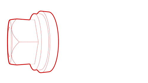
Contactor - Positive - HV Battery-Remove
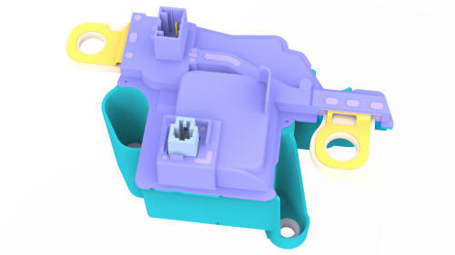
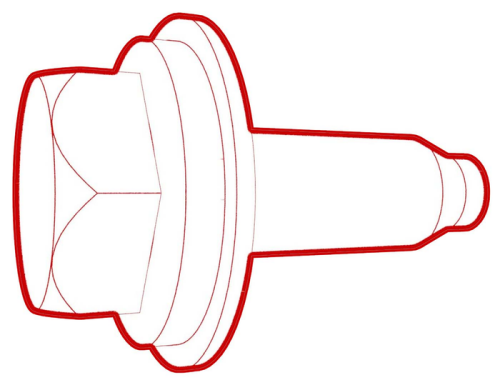
Contactor - Positive - HV Battery-Install
 Torque 8 Nm
 Torque 9 Nm
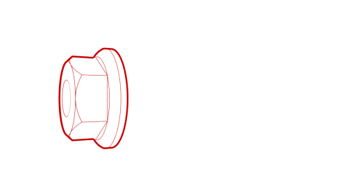
.jpg) Generic Measurement - Actual busbars and fasteners might appear
different
Generic Measurement - Actual busbars and fasteners might appear
different
 Torque 9 Nm
Generic Measurement - Actual busbars and fasteners might appear
different
Torque 9 Nm
Generic Measurement - Actual busbars and fasteners might appear
different
READ NEXT:
 Controller - High Voltage (Remove and Replace)
Controller - High Voltage- Remove
Warning: Only technicians who have been trained in High Voltage
Awareness are permitted to perform this procedure. Proper personal protective
equipment (PPE) and
SEE MORE:
Brake Fluid Bleed - One Caliper
SPECIAL TOOLS
Brake System Servicing Equipment (1054715-01-A)
Flare nut crowfoot set (1079041-00-A)
Adapter, Brake Bleeder, PowerProbe TS04
Armrest - Center Console (Remove and Replace)
Remove
Remove and attach the customer's belongings from the armrest, if needed.
Lower all the windows, and then move the LH and RH front seats forward.
Remove the center console lower rear panel. See
Panel - Lower Rear - Center Console (Remove and Replace).
Remove the center console air ven
