Tesla Model 3: HV Header - Inverter - Rear Drive Unit (Remove and Replace)
SPECIAL TOOLS
Extractor, Drive Unit HV Header, Model 3
(1142608-00-B)
Lever Lock, HV Connector, Model 3 (1140311-00-A)
Only technicians who have been trained in High
Voltage Awareness are permitted to perform this
procedure. Proper personal protective equipment (PPE)
and insulating HV gloves with a minimum rating of
class 0 (1000V) must be worn at all times a high
voltage cable, busbar, or fitting is handled. Refer to Tech
Note TN-15-92-003, "High Voltage Awareness Care Points" for
additional safety information.
Remove
Install
Note: Push, pull, and push on the header to make
sure it is fully seated.
Caution:
Make sure that the harness fits the connector
squarely and tightly.
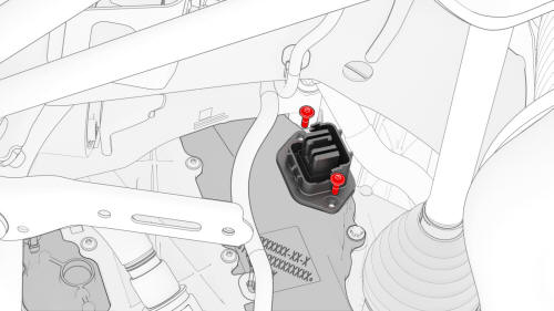
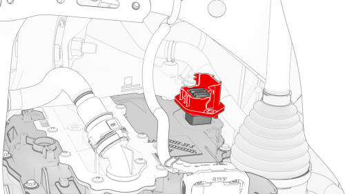
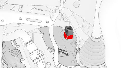
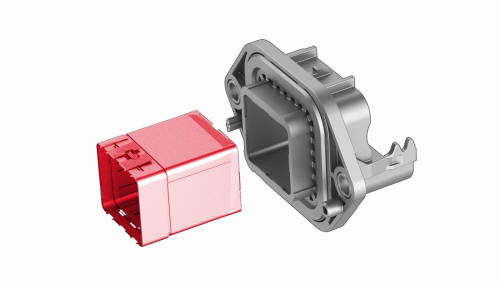
HV Header - Inverter - Rear Drive Unit - Remove
.jpg)
.png)
.jpg)
.png)
.png)
.png)
HV Header - Inverter - Rear Drive Unit - Install
.png) Torque 6 Nm
Torque 6 Nm
.png)
.png) Torque 6 Nm
Torque 6 Nm
READ NEXT:
 Inverter Air Leak Test
DRAFT
Warning: This procedure was derived from pre-production computer
models, and might not reflect the real-world situation. Warnings
and cautio
SEE MORE:
Brake Pad Kit - Front (Base Brakes) (Remove and Replace)
Remove
Remove the LH front wheel. See
Wheel (Remove and Install).
Remove the brake pad retaining pins that attach the anti-rattle spring
from the LH front brake caliper.
Remove the front brake pads from the LH front brake caliper.
Use the caliper spreader kit or similar tool to gently
Sensor - Parking Distance - Front - Each (Remove and Replace)
Remove
Remove the rear underhood apron. See Underhood Apron - Rear (Remove and
Replace).
Remove the cabin intake duct. See Duct - Cabin Intake (Remove and
Replace).
Remove the hood latch cover. See Cover - Hood Latch (Remove and Replace).
Remove the underhood storage unit. See Underhood S
