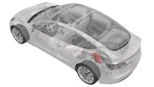
Tesla Model 3: Inverter Air Leak Test
DRAFT
Warning: This procedure was derived from pre-production computer models, and might not reflect the real-world situation. Warnings and cautions might be missing. Follow safety requirements and use extreme caution when working on or near high voltage systems and components.SPECIAL TOOLS
Kit, Inverter Leak Test Adapter, M3 (1450875-00-A)
Pack Enclosure Leak Tester, HV Battery (1026636-00-A)
Lever Lock, HV Connector, Model 3 (1140311-00-A)
Procedure
- Perform the vehicle electrical isolation procedure. See Vehicle Electrical Isolation Procedure.
- Remove the mid aero shield panel. See Panel - Aero Shield - Mid (Remove and Replace).
- Disconnect the signal harness from the inverter signal connector, and then install the leak test adapter plug into the connector.
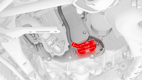
- Release the lock on the rear drive unit HV battery cable connector.
- Swing the release handle for the rear drive unit HV battery cable connector, and then disconnect the rear drive unit HV battery cable.
- Install the leak test adapter to the connector.
- Connect the pack enclosure leak tester to the leak test adapter on the HV electrical connector.
- Close both valves on the pack enclosure leak tester, and then connect a compressed air supply line.
- Fully close the regulator, and then open the inlet valve.
- Set the regulator to 1 psi.
- Open the outlet valve, and allow at least 45 seconds for the pressure to stabilize to 1 psi.
- Close the inlet valve, record the starting pressure displayed, and then start a 60-second timer.
- After 60 seconds record the ending pressure displayed.
- Subtract the ending pressure from the starting pressure, and if:
- The difference is greater than 0.04 psi, check the hose, adapter, and plug fittings, close the outlet valve and open the inlet valve, check the regulator pressure, and then retest from step 11. If the difference is still greater than 0.04 psi, escalate a Toolbox session.
- The difference is 0.04 psi or less, continue the procedure.
- Disconnect the air supply from the pack enclosure leak tester.
- Open the inlet valve, and then disconnect the pack enclosure leak tester from the leak test adapter on the HV electrical connector.
- Remove the leak test adapter from the rear drive unit HV electrical connector.
- Fully raise the handle on the rear drive unit HV electrical harness.
.png)
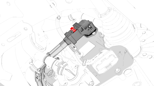
- Attach the HV connector lever lock onto the back of the HV electrical harness.
- Firmly connect the HV electrical harness to the inverter connector.
Caution: Make sure that the harness fits the connector squarely and tightly.
- While pressing the harness to the connector, remove the HV connector lever lock.
.png)
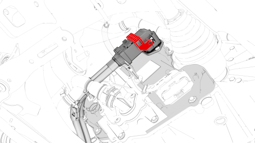
- While pressing the harness to the connector, fully lower the handle.
.png)
- Slide the release to lock the HV electrical harness.
- Remove the leak test adapter plug from the inverter signal connector, and then connect the signal harness to the connector.
- Install the mid aero shield panel. See Panel - Aero Shield - Mid (Remove and Replace).
- Connect 12V power. See 12V Power (Disconnect and Connect).
READ NEXT:
 Inverter Coolant Leak Test
DRAFT
Warning:
This procedure was derived from pre-production computer
models, and might not reflect the real-world situation. Warnings
and cautions might be mis
Inverter - Rear Drive Unit (Remove and
Install)
Inverter - Rear Drive Unit - Remove
SPECIAL TOOLS
Skt, 3/8in Dr, 10EP Torx Plus External (1130479-00-A)
SEE MORE:
Sensor - Wheel Speed - ABS - Rear - LH (Remove and Replace)
Remove
Remove the rear LH wheel. See Wheel (Remove and
Install).
Actuator - 5-Way Valve (Dual Motor) (Remove and Replace)
SPECIAL TOOLS
Kit, Svc Plug, Cooling Hose, Model 3 (1135762-00-A)
Wrench, Diverter Valve, Model 3 (1447556-00-A)
Remove
Remove the superbottle. See Superbottle (Dual Motor) (Remove and
Replace).
Remove the screws that attach the 5-way valve actuator to the 5-way
valve cover.
Remove
