Tesla Model 3: Inverter - Rear Drive Unit - Install
Install
- Secure the ESD strap to the replacement inverter housing.
.png)
- Inspect the condition of the gap pad on the inverter PCB. Replace the gap pad if it does not fulfill these criteria.
- New and undamaged condition.
- Fully covers the discharge resistor array and that no resistors are visible.
- Clean and free of debris.
- Evenly adhered to the inverter PCB.
- Install a new inverter gasket.
- Use an IPA wipe to clean the HV mating surfaces of the motor and inverter 3-phase terminals.
- Carefully align the inverter to the 2 pins in the rear drive unit, and then install the inverter to the rear drive unit. Make sure that the 3-phase terminals align during installation.
Caution: Avoid damage to the printed circuit board of the inverter.
.png)
- Hand-tighten the new bolts (x12) that attach the inverter to the gearbox assembly.
.jpg)
- Torque the bolts in the sequence shown.
.png) Torque 5 Nm +20 deg
Torque 5 Nm +20 deg
.png)
- Install the new bolts (x3) that attach the 3 phase cable to the inverter assembly.
- Tighten the bolts to this specification.
.png) Torque 11.5 Nm
Torque 11.5 Nm
- Loosen the bolts 180 degrees.
- Tighten the bolts to this specification.
.png) Torque 5 Nm +40 deg
Torque 5 Nm +40 deg
.png)
- Apply a film of ATF-9 fluid to the walls of the gear case bores, and then install the new 3-phase access cover.
.png)
- Install the bolts (x2) that attach the 3-phase
access cover to the rear drive unit assembly.
.png) Torque 7.5 Nm
Torque 7.5 Nm
- Perform an inverter air leak test. See Inverter Air Leak Test.
.png)
- Apply a new 3-phase access label.
- Remove the ESD wrist strap.
- Fully raise the handle on the rear drive unit HV electrical harness.
.png)
- Attach the HV connector lever lock onto the back of the HV electrical harness.
- Firmly connect the HV electrical harness to the inverter connector.
Caution: Make sure that the harness fits the connector squarely and tightly.
- While pressing the harness to the connector, remove the HV connector lever lock.
.png)
- While pressing the harness to the connector, fully lower the handle.
.png)
- Slide the release to lock the HV electrical harness.
.png)
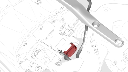
- Install the bolt that attaches the HV harness
bracket to the inverter.
.png) Torque 6 Nm
Torque 6 Nm
.png)
- Connect the rear drive unit inlet hose to the inverter coolant inlet, and then fasten the clip.
Caution: Perform a push-pull test to verify that the hose is fully seated.
.jpg)
- Fasten the clip that attaches the rear drive unit inlet hose to the HV harness bracket.
- Connect the electrical harness to the inverter low voltage connector.
- Install the LH rear drive unit mount. See Mount - Rear Drive Unit - LH (Remove and Replace).
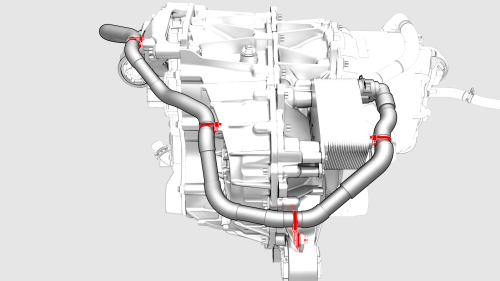
- Fasten the clips that attach the upper cooler hose to the rear drive unit.
- Install the rear subframe assembly. See Subframe Assembly - Rear (Remove and Install).
- Refill the cooling system. See Powertrain Coolant (Drain and Refill). Note: Perform the refill before the installation of the front RH wheel liner.
- Within Toolbox, return to the Rear Drive Inverter - Remove and Replace Autodiag, and run PROC_PM_X_RESTORE-DATA-BOOT to restore the bootloader data and run PROC_PM_X_WRITE-DRIVE-TYPE to configure the Usage ID.
- Use the Rear Drive Inverter - Remove and Replace Autodiag to:
- Redeploy the current firmware to the new inverter.
- Restore the required data to the new inverter.
- Perform the resolver learn process. Caution: This process requires the vehicle wheels to be spinning at 55 mph (90 kph) while elevated on a lift.
- Perform the thermal performance self-test.
- Perform a four wheel alignment. See Four Wheel Alignment (Check and Adjust).
READ NEXT:
 Powertrain Coolant - Drain
SPECIAL TOOLS
Drive Unit Pressure Test Fixture (1053600-00-C)
Kit, Coolant Leak Test Adapters, Model 3
(1132
Powertrain Coolant - Refill
Refill
Remove the plugs from the hoses.
SEE MORE:
Fascia - Front (Remove and Replace)-Install
Install
Installation procedure is the reverse of removal.
Top
Bottom
Install the front fascia grille onto the front fascia, and then fasten
the clips (x9) that attach the grille to the fascia.
Install the screws that attach the front fascia grille to the front
fascia.
Torque 1.8 Nm
Controls
Overview
Touch Controls on the bottom
corner of the touchscreen to control features and
customize Model 3 to suit your preferences. The Controls window appears over the
map. Touch an option on the left side of the window to display the associated
controls and settings. By default, Quick Contro
