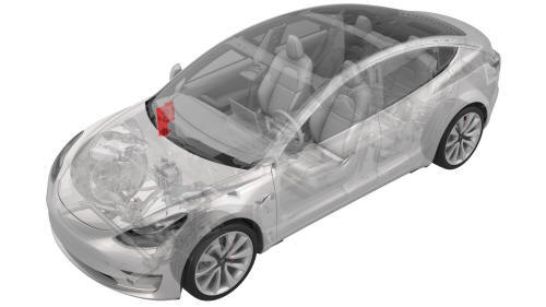
Tesla Model 3: Module - Body Controller - RH (Remove and Replace)
Module - Body Controller - RH - Remove
Remove
- On the touchscreen, power off the climate control system, and wait at
least 30 seconds for the climate control system to completely shut down.
- Remove the 2nd row lower seat cushion. See Seat Cushion - Lower - 2nd
Row (Remove and Replace).
- Remove the rear underhood apron. See Underhood Apron - Rear (Remove and
Replace).
Caution: Do not proceed until the climate control system has been
powered off for at least 30 seconds. Do not disconnect 12V power while the
climate control system is operational.
- Disconnect 12V power. See 12V Power (Disconnect and Connect).
- Remove the LH instrument panel end cap. See End Cap - Instrument Panel -
LH (Remove and Replace).
- Remove the LH air wave end cap. See End Cap - Air Wave - LH (Remove and
Replace).
- Remove the RH instrument panel end cap. See End Cap - Instrument Panel -
LH (Remove and Replace).
- Remove the RH air wave end cap. See End Cap - Air Wave - LH (Remove and
Replace).
- Remove the main instrument panel decor trim. See Decor Trim - Instrument
Panel - Main (Remove and Replace).
- Remove the RH middle A-pillar trim. See Trim - A-Pillar - Middle - LH (Remove
and Replace).
- Remove the RH lower A-pillar trim. See Trim - A-Pillar - Lower - LH (Remove
and Replace).
- Remove the passenger footwell cover. See Cover - Footwell - Passenger (LHD)
(Remove and Replace).
- Remove the front passenger knee airbag. See Airbag - Knee - Front
Passenger (Remove and Replace).
- Remove the glove box. See Glove Box (LHD) (Remove and Replace).
- Remove the RH front floor mat.
- Remove the RH center console side panel carpet. See Carpet - Side Panel
- Center Console - LH (Remove and Replace).
- Release the clips that attach the RH front carpet to the RH footwell.
- Fold back the RH front carpet.
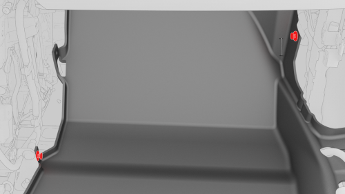
- Remove the nuts that attach the RH side carpet locator bracket to the
vehicle, and then remove the RH side carpet locator bracket from the vehicle.
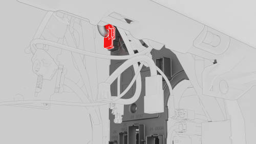
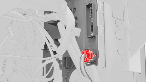
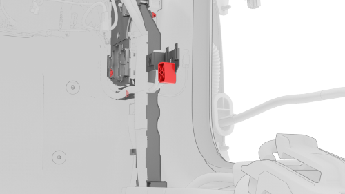
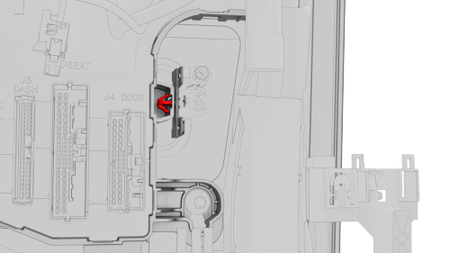
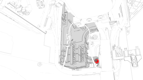
- Disconnect the electrical connectors from the RH body controller module.
- Release the lock, and then disconnect the RH front door electrical
connector from the RH body controller module.
- Release the lock, and then disconnect the front passenger seat
electrical connector from the RH body controller module.
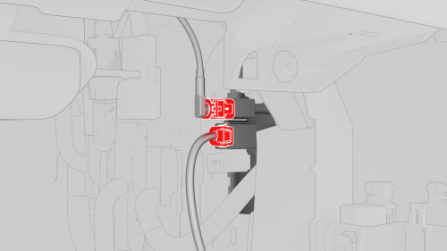
- Disconnect the instrument panel harness coaxial cable from the RH body
controller module.
- Disconnect the instrument panel electrical connector from the RH body
controller module.
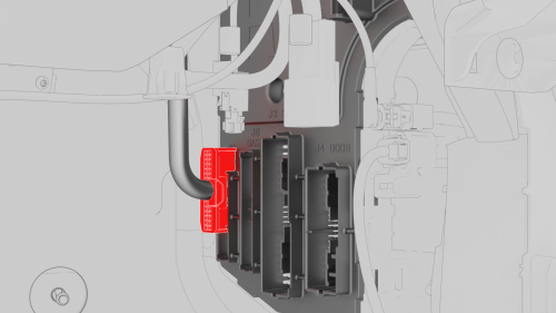
- Disconnect the HVAC connector from the RH body controller module.
- Disconnect the front harness connector from the RH body controller
module.
- Release the clip that attaches the inline electrical connector to the RH
body controller module, and then disconnect the electrical connector.
.png)
- Remove and discard the nuts that attach the electrical wiring to the RH
body controller module, and remove the electrical wiring from the RH body
controller module.
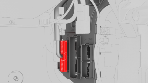
- Release the electrical harness clips (x2) from underneath the IP carrier.
- Release the lock, and then disconnect the body 2 electrical connector
from the RH body controller module.
- Release the lock, and then disconnect the body 1 electrical connector
from the RH body controller module.
Caution: To avoid damage, carefully remove the body 1 electrical
connector because the lock may get hung up on the IP carrier.
- Release the lock, and then disconnect the body 3 electrical connector
from the RH body controller module.
- Disconnect the 3 inline electrical connectors at the RH lower A-pillar
area.
- Release the clip that attaches the electrical harness to the RH lower
A-pillar area.
- Release the clips that attach the RH body electrical harness to the RH
body controller module.
- Move the RH body harness away from the RH body controller module.
- Release the clip that attaches the wiring harness to the RH body
controller module.
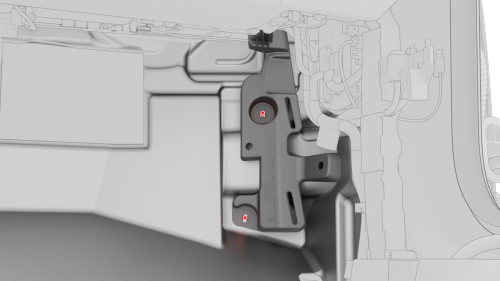
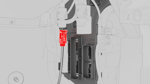
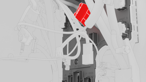
- Remove and discard the nut that attaches the RH body controller module
to the body.
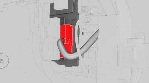
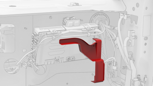
- Slide the RH body controller upwards to release the W-clip, then move
the RH body controller out from underneath the instrument panel, and then
remove the RH body controller from the vehicle.
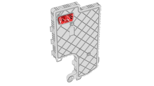
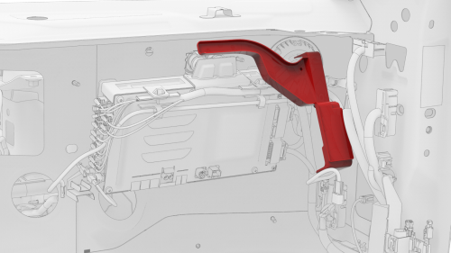
- If the RH body controller module has a shroud installed, release the
clips that attach the shroud to the module.
Module - Body Controller - RH - Install
Install
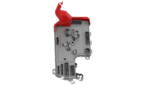
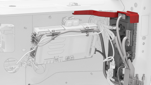
- Position the shroud by itself in position on the vehicle.
Note: Position the shroud vertical and move it up above the
computer, and then pivot the lower edge so that the shroud sits horizontally.
- Maneuver the RH body controller module into position under the IP
carrier, and then install the 2 clips that attach the shroud to the module.
Note: Make sure that both clips are fully seated.
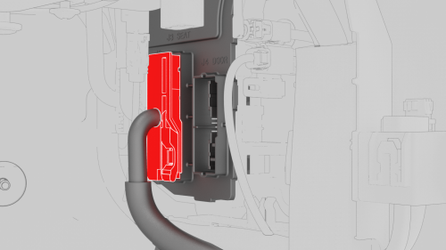
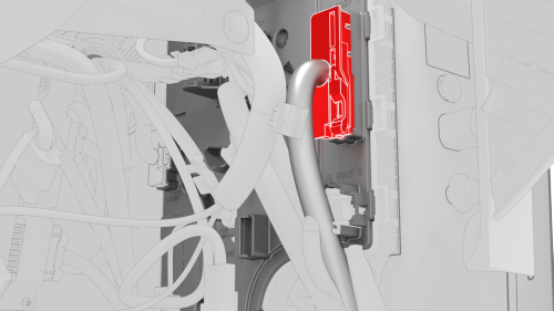
- Align the W-clip with the body cutout, and then slide down to attach the
RH body controller to the body.
.png)
- Install new nut that attaches the RH body controller to the body.
.png)
- Install the clip that attaches the wiring harness to the RH body
controller.
.png)
- Move the RH body harness towards the right side of the RH body
controller, and then install attach the harness clips (x4) to the RH body
controller.
.png)
- Install the clip that attaches the RH body harness at the lower A-pillar
area.
- Connect the wiring harnesses at the RH lower A-pillar clip.
.png)
- Connect the body 3 electrical connector onto the RH body controller
module.
Note: Make sure that the body 3 electrical connector lock is fully
engaged.
.png)
- Connect the body 1 electrical connector onto the RH body controller
module.
Note: Make sure that the body 1 electrical connector lock is fully
engaged.
- Connect the body 2 electrical connector onto the RH body controller
module.
Note: Make sure that the body 2 electrical connector lock is fully
engaged.
- Install the harness clips (x2) onto the lower IP carrier.
.png)
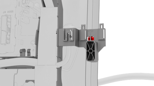
- Install new nuts (x2) that attach the positive cables onto the RH body
controller module.
.png)
- Connect the inline electrical connector, and then attach it to the RH
body controller module.
.png)
- Connect the front wiring harness electrical connector onto the RH body
controller module.
.png)
- Connect the HVAC electrical connector onto the RH body controller module.
.png)
- Connect the instrument panel electrical connector onto the RH body
controller module.
.png)
- Connect the instrument panel harness coaxial cable onto the RH body
controller module.
.png)
- Connect the front passenger seat electrical connector onto the RH body
controller module.
Note: Make sure that the front passenger seat electrical connector
lock is fully engaged.
.png)
- Connect the RH front door electrical connector onto the RH body
controller module.
Note: Make sure that the RH front door electrical connector lock is
fully engaged.
.png)
- Connect the RH front door wiring connectors onto the RH body controller
module.
.png)
- Install the nuts that attach the RH carpet locator bracket onto the
vehicle. Torque
2.5 Nm
- Fold the RH front carpet back to its original position.
.png)
- Install the clips that attach the RH front carpet to the footwell area.
- Install the RH center console side panel carpet. See Carpet - Side Panel
- Center Console - LH (Remove and Replace).
- Install the RH front floor mat.
- Install the glove box. See Glove Box (LHD) (Remove and Replace).
- Install the front passenger knee airbag. See Airbag - Knee - Front
Passenger (Remove and Replace).
- Install the passenger footwell cover. See Cover - Footwell - Passenger (LHD)
(Remove and Replace).
- Install the RH lower A-pillar trim. See Trim - A-Pillar - Lower - LH (Remove
and Replace).
- Install the RH middle A-pillar trim. See Trim - A-Pillar - Middle - LH (Remove
and Replace).
- Install the main instrument panel decor trim. See Decor Trim -
Instrument Panel - Main (Remove and Replace).
- Install the RH air wave end cap. See End Cap - Air Wave - LH (Remove and
Replace).
- Install the RH instrument panel end cap. See End Cap - Instrument Panel
- LH (Remove and Replace).
- Install the LH air wave end cap. See End Cap - Air Wave - LH (Remove and
Replace).
- Install the LH air wave end cap. See End Cap - Air Wave - LH (Remove and
Replace).
- Connect 12V power. See 12V Power (Disconnect and Connect).
Caution: Do not power on the climate control system until the
firmware has been updated, the seat and window calibration has been performed,
and this procedure has been fully completed.
- Install the rear underhood apron. See Underhood Apron - Rear (Remove and
Replace).
- Install the 2nd row lower seat cushion. See Seat Cushion - Lower - 2nd
Row (Remove and Replace).
- Update the vehicle firmware.
- Connect a laptop with Toolbox to the vehicle.
- Using Toolbox, type Seat in the search field.
Note: Make sure that Actions is selected in Toolbox, if not already.
- Using Toolbox, click the play button next to PROC_VCRIGHT_SEAT-CALIBRATE,
and then select Run.
- Using Toolbox, type Window in the search field.
Note: Make sure that Actions is selected in Toolbox, if not already.
- Using Toolbox, click the play button next to PROC_VCLEFT-VCRIGHT_
X_WINDOW-CALIBRATION, and then select Run.
- Disconnect the laptop from the vehicle.
READ NEXT:
Remove
Remove the front fascia. See Fascia - Front (Remove and Install).
Disconnect the electrical connector from the HomeLink transmitter module.
Release the tab, and then slide the H
SEE MORE:
Warning:
Only technicians who have been trained in High Voltage Awareness are
permitted to perform this procedure. Proper personal protective equipment (PPE)
and insulating HV gloves with a minimum rating of class 0 (1000V) must be worn
at all times a high voltage cable, busbar, or fitting is ha
Adjust Headlights Using a Headlight Tester
Park the vehicle on a level surface.
Make sure that all 4 tires are inflated to specification.
Open the front trunk hood.
On the touchscreen, enter headlight adjustment mode: Controls > Service
> Adjust Headlights.
Turn on the headlights.
 Module - HomeLink Transmitter (Remove and Replace)
