Tesla Model 3: Module - Cooling Fan (Remove and Install)
Module - Cooling Fan- Remove
Remove
- Raise and support the vehicle. See
Raise Vehicle - 2 Post Lift
- Remove the 2nd row lower seat cushion. See
Seat Cushion - Lower - 2nd Row (Remove and Replace).
- Remove the rear underhood apron. See
Underhood Apron - Rear (Remove and Replace).
- Remove the cabin intake duct. See
Duct - Cabin Intake (Remove and Replace).
- Remove the outer HVAC plenum duct. See
Duct - HVAC Plenum - Outer (Remove and Replace).
- Remove the hood latch cover. See
Cover - Hood Latch (Remove and Replace).
- Remove the underhood storage unit. See
Underhood Storage Unit (Remove and Replace).
- Perform the A/C refrigerant recovery. See
A/C Refrigerant (Recovery and Recharge).
- Disconnect 12V power. See
12V Power (Disconnect and Connect).
- Disconnect the active grille shutter electrical connector.
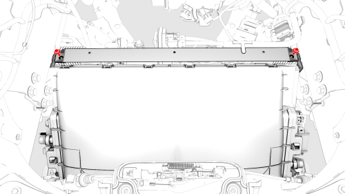
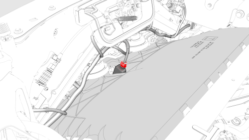
- Remove the bolts that attach the underhood storage unit reinforcement
bracket to the cooling fan, and then slide the reinforcement bracket aside
for clearance
- Remove the front aero shield panel. See
Panel - Aero Shield - Front (Remove and Replace).
- Remove the front fascia valance. See
Valance - Front Fascia (Remove and Replace).
- Disconnect the electrical harness from the cooling fan module connector.
- Place coolant drain container underneath the LH front side of the
vehicle.
- Release the clip that attaches the radiator inlet hose to the cooling
fan module, remove the hose, and then plug the hose.
- Place coolant drain container underneath the RH front side of the
vehicle.
- Release the clip that attaches the radiator outlet hose from the cooling
fan module, remove the hose, and then plug the hose.
- Remove the coolant drain container from underneath the vehicle.
Note: Make sure that the refrigerant has fully recovered before
continuing this procedure.
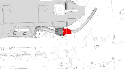
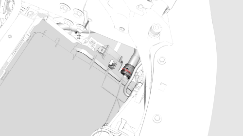
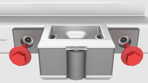
- Remove the nut that attaches the suction/liquid line to the cooling fan
module, and then disconnect the A/C suction line.
- Remove and discard the O-ring from the suction/liquid line.
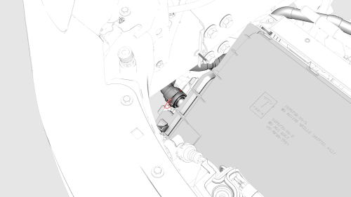
- Remove the nut that attaches the discharge line to the cooling fan
module, and then disconnect the discharge line.
- Remove and discard the O-ring from the discharge line.
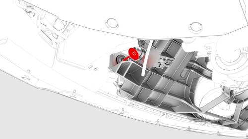
LH Side
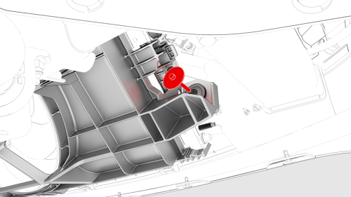
RH Side
Module - Cooling Fan - Install
Install
.png)
LH Side
.png)
RH Side
- With an assistant, put the cooling fan module into position from below
the vehicle, and then hand-tighten the bolts that attach the bottom of the
cooling fan module to the ankle catcher.
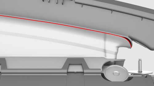
Note: Make sure that the lower seal from the cooling fan module and
lower active shutter grille are sitting flush against each other.
- Tighten the LH and RH bolts that attach the lower portion of the cooling
fan module to the ankle catcher.
 Torque 10 Nm
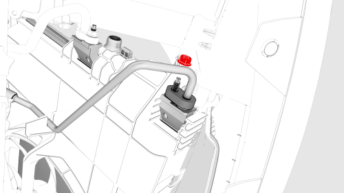
- Install a new o-ring onto the discharge line, and then install the
discharge line into the cooling fan module.
.png)
- Install the nut that attaches the discharge line to the cooling fan
module.
 Torque 22 Nm
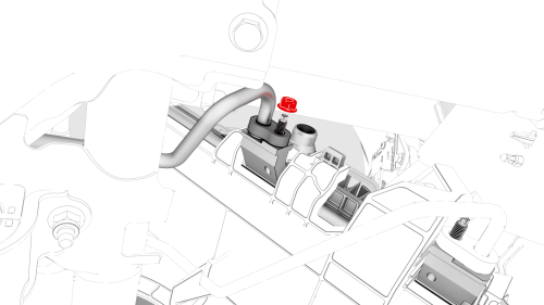
- Install a new o-ring onto the suction/liquid line, and then install the
suction line into the cooling fan module.
- Install the nut that attaches the suction/liquid line to the cooling fan
module.
Torque 22 Nm
.png)
- After installing the suction/liquid line, recharege the refrigerant. See
A/C Refrigerant (Recovery and Recharge).
Note: Perform installation of components removed concurrently with
refrigerant recharge.
- Position the coolant drain underneath the RH side of the vehicle.
.png)
- Remove the hose plug, and then install the radiator outlet hose to the
cooling fan module. Secure the hose with clip.
- Position the coolant drain underneath the LH side of the vehicle.
.png)
- Remove the hose plug, and then install the radiator inlet hose to the
cooling fan module. Secure the hose with clip.
- Remove the coolant drain container from underneath the vehicle.
.png)
- Connect the electrical harness to the cooling fan connector.
- Install the front valance. See Valance - Front Fascia (Remove and
Replace).
- Install the front aero shield panel. See Panel - Aero Shield - Front (Remove
and Replace).
- Lower the vehicle fully.
- Slide the underhood reinforcement bracket onto the top of the cooling
fan module.
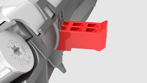
Note: The cooling fan module tab must be inserted into the isolator
so that the trailing tab touches the isolator rubber and the chamfered edge is
clearly visible when looking from above.
Note: The trailing edge of the cooling fan module mount must
contact the lower tunnel of the isolator.
.png)
- Install the bolts that attach the underhood reinforcement bracket to the
body. Torque 16 Nm
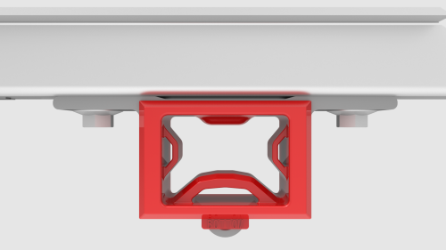
Note: Make sure that there is space between the cooling fan module
and the isolator bar to avoid vibration.
- Loosen the bolts that attach the LH side cooling fan module isolator.
- Push the LH side of the cooling fan module isolator towards the front of
the vehicle until the isolator bottoms out at the top.
- Tighten the bolts that attach the LH side cooling fan module isolator.
 Torque 6 Nm
- Repeat step 19 through step 21 for the RH side cooling fan module
isolator.
- Check the coolant level at the superbottle and add coolant to the full
line, if needed.
.png)
- Connect the active grille shutter electrical connector.
- Connect 12V power. See 12V Power (Disconnect and Connect).
- After the A/C refrigerant recharge has fully completed, verify the
operation of the A/C system.
- Perform the cooling system vacuum refill. See Cooling System (Vacuum
Refill).
- Install the underhood storage unit. See Underhood Storage Unit (Remove
and Replace).
- Install the hood latch cover. See Cover - Hood Latch (Remove and Replace).
- Install the outer HVAC plenum duct. See Duct - HVAC Plenum - Outer (Remove
and Replace).
- Install the cabin intake duct. See Duct - Cabin Intake (Remove and
Replace).
- Install the rear underhood apron. See Underhood Apron - Rear (Remove and
Replace).
READ NEXT:
Remove
Remove the cooling fan module. See Module - Cooling Fan (Remove and
Install).
Release the clips (x14) that attach the active grille shutter to the
cooling fan module, and then re
SEE MORE:
Procedure
Special tools required for this procedure:
SPECIAL TOOLS
Pliers, Clip Removal (1133569-00-A)
On a wall, measure 14.5 in (36.8 cm) from the floor, and then apply a
length of 1-inch masking tape horizontally to the wall to mark the
measurement.
Measure 25 ft (7.62 m) from the wall,
Remove
Remove the rear fascia. See
Fascia - Rear (Remove and Install).
Press downward at the top to release the tabs that attach the air
extractor to the body, then swing the upper portion of the air extractor
outwards, and then remove the air extractor from the vehicle.
Install
P
 Module - Cooling Fan (Remove and Replace)
