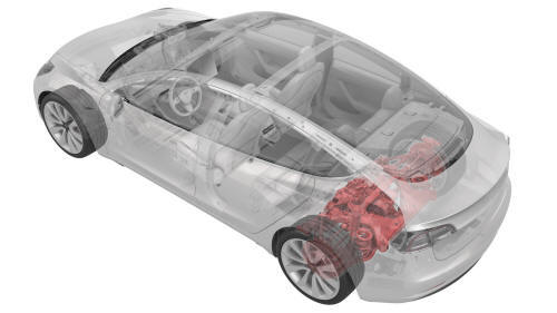
Tesla Model 3: Subframe Assembly - Rear - Remove
Tesla Model 3 2017-2026 Service Manual / Chassis / Subframe Assembly - Rear (Remove and Install) / Subframe Assembly - Rear - Remove
SPECIAL TOOLS
Kit, EPB Release, Handheld (1134520-00-A)
XP-10 Power Supply, XP-10 (1129348-00-A)
Fixture, Subframe, Model 3 (1099645-00-B)
Lever Lock, HV Connector, Model 3 (1140311-00-A)
Remove
- Use Toolbox to release the rear parking brakes. See Parking Brake - Caliper - Rear - LH (Release).
- Raise and support the vehicle. See Raise Vehicle - 2 Post Lift.
- Remove the rear underhood apron. See Underhood Apron - Rear (Remove and Replace).
- Remove the 2nd row lower seat cushion. See Seat Cushion - Lower - 2nd Row (Remove and Replace).
- Disconnect 12V power. See 12V Power (Disconnect and Connect).
- Perform the vehicle electrical isolation procedure. See Vehicle Electrical Isolation Procedure.
.png)
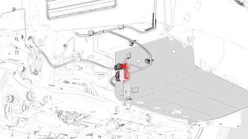
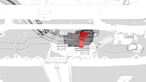
- Remove the HV cap that covers the HV harness located on the LH side of the penthouse.
- Remove the LH 2nd row seat side bolster. See Bolster - Side - Seat - 2nd Row - LH (Remove and Replace).
- Remove the LH rear sill panel trim. See Trim - Sill Panel - Rear - LH (Remove and Replace).
.jpg)
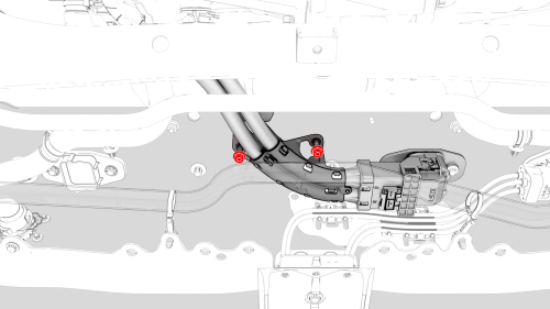
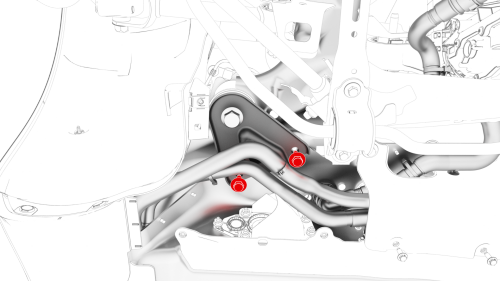
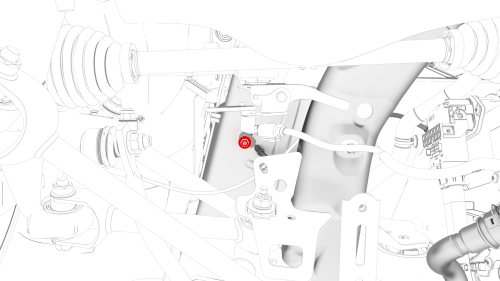
- Remove the bolts that attach the wiring harness bracket at the penthouse.
- Release the clips that attach the wiring harness bracket, and then remove the bracket from the vehicle.
.jpg)
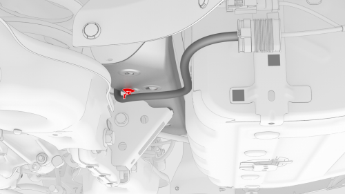
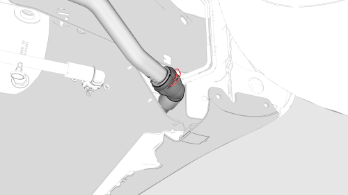
- Release the clip that attaches the wiring harness to the LH lower C-pillar.
.jpg)
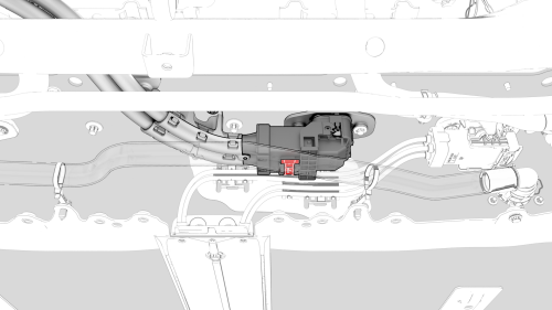
- Raise the handle to disconnect the electrical harness from the DC Input assembly.
- Remove the LH and RH rear wheels. See Wheel (Remove and Install).
- Remove the LH and RH wheel arch liners. See Wheel Arch Liner - Rear - LH (Remove and Replace).
- Raise the vehicle fully.
- Remove the front aero shield panel. See Panel - Aero Shield - Front (Remove and Replace).
- Drain the powertrain coolant. See Powertrain Coolant (Drain and Refill).
- Remove the mid aero shield panel. See Panel - Aero Shield - Mid (Remove and Replace).
- Remove the rear fascia diffuser. See Diffuser - Rear Fascia (Remove and Replace).
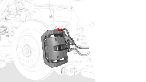
- Disconnect the electrical connector from the LH rear brake caliper.
LH shown, RH similar
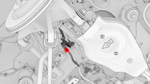
- Check the LH rear upper aft link and if present, disconnect the electrical connector from the sensor.
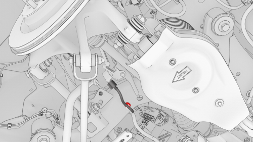
- If a connector was disconnected in the previous step, release the clip that attaches the connector harness to the underside of the rear subframe.
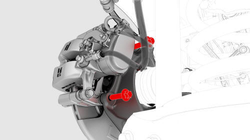
- Remove the bolts that attach the LH rear brake caliper bracket to the knuckle, and then hang the caliper bracket on the body with an S-hook.
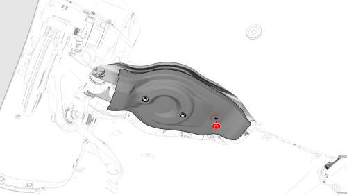
- Remove the bolt that attaches the cover to the LH lower aft link, and then remove the cover from the vehicle.
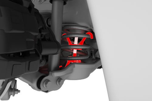
- Install a spring compressor onto the LH rear coil spring.
Caution:
Line up the hooks per image and verify that the threaded shaft goes through the body opening when the suspension is compressed
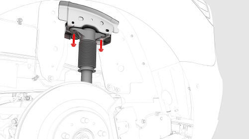
- Remove the bolts that attach the LH rear damper at the top mount.
- Disconnect the electrical harness from the LH 12V subframe connectors.
- Remove the LH subframe electrical harness clip from the body.
- Repeat step 21 through step 29 for the RH side of the vehicle.
- Remove the rear HV battery skid plate. See Skid Plate - HV Battery - Rear (Remove and Replace).
.png)
- Release the clips that attach the RH inner HV battery return hose to the HV battery.
- Position the coolant drain beneath the LH rear of the HV battery.
.png)
- Disconnect the rear drive unit inverter inlet hose from the LH side of the HV battery, and then plug the male and female fittings.
- Release the barrel clip that attaches the rear drive unit inverter inlet hose to the HV battery, and separate the hose from the battery.
- Remove the nuts (x2) that attach the HV battery to rear drive unit harness bracket to the HV battery.
- Slide the release to unlock the HV electrical harness connector on the HV battery.
- Lift the handle on the HV electrical harness connector, disconnect the harness from the HV battery connector.
- Position the coolant drain beneath the RH rear of the HV battery.
- Release the clip, disconnect the rear drive unit outlet hose from the powertrain return hose, and then plug the male and female fittings.
- Remove the coolant drain container from underneath the vehicle.
.png)
- Release the fir tree clips that attach the coolant hoses to the LH shear plate.
- Remove the smaller bolts that attach the LH shear plate to the HV battery.
- Repeat step 42 and step 43 for the RH shear plate.
- Remove the nut that attaches the rear drive unit ground strap to the body.
- Remove the rear stabilizer bar. See Stabilizer Bar - Rear (Remove and Replace).
- Place the rear subframe lifting tool into position underneath the rear subframe.
- Attach an air hose to the rear subframe lifting tool.
- With an assistant, raise the rear subframe lifting tool to support the rear subframe.
- Loop the straps over the rear subframe, hook the ends of the straps to the metal rings, and then pull the straps tight to restrain the subframe to the rear subframe lifting tool.
Note: Lower the vehicle to give more slack to connect the straps to the rings, if necessary.
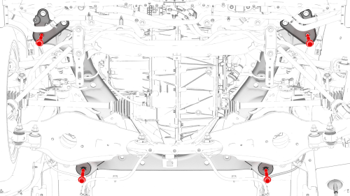
- Remove and discard the bolts that attach the shear plates and rear subframe to the body.
Note: When the front bolts are removed, the shear plates are also removed.
- With an assistant, slowly lower the rear subframe lifting tool to remove the rear subframe from the vehicle.
Caution: Assist with the routing of HV harnesses and coolant hoses through components so that they do not "catch".
- Disconnect the air supply from the rear subframe lifting tool.
- Move the rear subframe and rear subframe lifting tool away from the
vehicle.
READ NEXT:
 Subframe Assembly - Rear - Install
Install
Position the subframe lifting tool and subframe underneath the vehicle.
Connect the air line to the subframe lifting tool.
With an assistant, slowly raise the rear drive unit and subframe
Subframe Assembly - Rear - Remove
SPECIAL TOOLS
Fixture, Subframe, Model 3 (1099645-00-B)
Lifting Sling, Drive Unit, Model 3 (NA, APAC) (1130279-00-A)
Adapter, Subframe, Body Shop, Model 3 (1130481-00-A)
Tool, Hub Puller, Hydraulic
SEE MORE:
Actuator - Vent - RH (Remove and Replace)
Remove
Remove the RH front vent. See
Vent - Front - RH (Remove and Replace).
Remove the screws that attach the RH vent actuator to the RH front vent,
and then remove the actuator from the vent.
Torque 1.3 Nm
Install
Installation procedure is the reverse of removal.
Jacking and Lifting
Follow the steps below to lift Model 3. Ensure
that any non-Tesla repair facility is aware of
these lifting points.
Position Model 3 centrally between the lift
posts.
Position the lift arm pads under the
designated body lift points at the
locations shown.
Warning: DO NOT position th
© 2019-2026 Copyright www.tmodel3.com
