Tesla Model 3: 12V Power (Disconnect and Connect)
SPECIAL TOOLS Cap, Logic Conn, Inv, 3DU (1108272-00-B) Warning: This procedure disables 12V power, but does not verify that
high voltage power is no longer available to high voltage components (PTC heater,
A/C compressor, inverters, etc). Perform
Vehicle Electrical Isolation Procedure after this procedure, and before
servicing high voltage components. Disconnect Warning: Prepare for these conditions before disconnecting 12V power: Caution: Do not proceed until the climate control system has been powered off
for at least 30 seconds. Do not disconnect 12V power while the climate control
system is operational.
Note: The HV battery positive contactor and negative contactor open
with a clunk sound.
Connect
12V Power- Disconnect
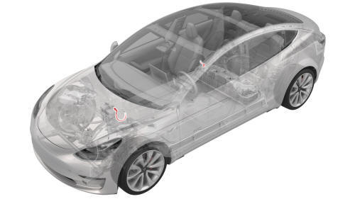
.jpg)
.png)
.jpg)
.jpg)
12V Power - Connect
.jpg) Torque 6 Nm
Torque 6 Nm
READ NEXT:
 Battery - 12V (Remove and Replace)
Remove
Remove the 2nd row lower seat cushion. See
Seat Cushion - Lower - 2nd Row (Remove and Replace).
Remove the rear underhood apron. See
Underhood Apron - Rear (Remove and Replace).
Remove
SEE MORE:
Harness - Main Front (Remove and Replace)
Harness - Main Front- Remove
Remove
Open the front LH and front RH doors
Open the hood.
Place wheel chocks on both rear wheels.
Put vehicle in Neutral.
Disconnect 12V power. See 12V Power (Disconnect and Connect).
Remove the LH lower A-pillar trim. See Trim - A-Pillar - Lower - LH
(Remove
Sensor - Temperature - RH (Remove and Replace)
Remove
Remove the RH center console side panel carpet. See
Carpet - Side Panel - Center Console - LH (Remove and Replace).
Disconnect the electrical wiring harness conector from the RH
temperature sensor.
Release the tabs that attach the RH temperature sensor to the HVAC
module,
