Tesla Model 3 Owners & Service Manuals

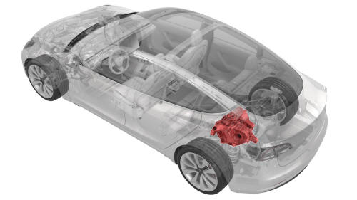
Tesla Model 3: Drive Unit - Rear (Remove and Install)

Drive Unit - Rear- Remove

 Drive Unit - Rear (Remove and Install)

SPECIAL TOOLS

Fixture, Subframe, Model 3 (1099645-00-B)

Lifting Sling, Drive Unit, Model 3 (NA, APAC) (1130279-00-A)

Adapter, Subframe, Body Shop, Model 3 (1130481-00-A)

Tool, Hub Puller, Hydraulic (1096075-00-A)

Tool, Axle Extraction, Model 3 (1133386-00-A)

Lever Lock, HV Connector, Model 3 (1140311-00-A)

Kit, Drive Unit Dipstick, Model 3 (1446276-00-B)

Remove

  1. Remove the rear subframe assembly. See Subframe Assembly - Rear (Remove and Install).

  Drive Unit - Rear- Remove

  1. Disconnect the electrical harness from the inverter low voltage connector.

  Drive Unit - Rear- Remove

  1. Release the clip that attaches the low voltage electrical harness to the inverter.

  Drive Unit - Rear- Remove

  1. Release the clip, disconnect the rear drive unit inlet hose from the inverter coolant inlet, and then plug the inlet.

  Drive Unit - Rear- Remove

  1. Release the clip that attaches the rear drive unit inlet hose to the HV harness bracket, and then remove the hose from the rear drive unit.

  Drive Unit - Rear- Remove

  1. Remove the bolt that attaches the HV harness bracket to the inverter.

  Drive Unit - Rear- Remove

  1. Slide the release to unlock the HV harness connector.

  Drive Unit - Rear- Remove

  1. Lift the handle on HV harness connector, disconnect the harness from the inverter connector, and then remove the harness from the rear drive unit.
  2. Drain the fluid from the rear drive unit. See Gearbox Fluid - Rear Drive Unit (Drain and Refill).

  Drive Unit - Rear- Remove

  1. Release the clip that attaches the LH rear ABS wheel speed sensor connector to the subframe, and then disconnect the subframe harness from the connector.

 Tip: Use a mechanical pickup tool to hold the connector in place, and then release the connector clip with a screwdriver.

  Drive Unit - Rear- Remove

  1. Release the clip and remove the grommet that attach the rear LH ABS wheel speed sensor cable to the rear knuckle and bracket.

  Drive Unit - Rear- Remove

  1. Remove and discard the bolt that attaches the rear LH ABS wheel speed sensor to the knuckle, and then remove the sensor from the knuckle.

  Drive Unit - Rear- Remove

  1. Remove and discard the nut, and then remove the washer that attach the LH halfshaft to the hub assembly.

  Drive Unit - Rear- Remove

  1. Remove the bolt that attaches the LH rear brake rotor to the hub. Note: Remove the lug nut previously installed for early production vehicles.
  2. Install the hub puller onto the LH rear rotor, and then install and hand-tighten the puller washers (x5) and the lug nuts (x5) onto the rotor studs.
  3. Use the hub puller to free the LH rear halfshaft from the hub splines. Note: The LH rear halfshaft is removed in a later step.
  4. Remove the lug nuts (x5) and the puller washers (x5) from the LH rear rotor studs, and then remove the hub puller from the rotor.

  Drive Unit - Rear- Remove

  1. Install the bolt that attaches the LH brake rotor to the hub. Torque 5 Nm

 Note: Reinstall the lug nut previously installed for early production vehicles.

  Drive Unit - Rear- Remove

  1. Remove the bolt and nut that attach the LH upper aft link to the knuckle.

  Drive Unit - Rear- Remove

  1. Remove the bolt and nut that attach the LH upper fore link to the knuckle.

  Drive Unit - Rear- Remove

  1. Remove the bolt and nut that attach the LH rear toe link to the knuckle.
  2. Remove the LH rear halfshaft from the knuckle and hub assembly.
  3. With an assistant, release the LH rear halfshaft from the rear drive unit. Note: Set the LH rear halfshaft on the LH aft lower control arm.
  4. Remove the LH halfshaft from the rear drive unit, and then install a halfshaft plug into the opening of the gearbox.
  5. Repeat step 10 through step 24 on the RH side of the rear drive unit.

  Drive Unit - Rear- Remove

  1. Disconnect the electrical harness from the resolver connector.

  Drive Unit - Rear- Remove

  1. Disconnect the electrical harness from the oil pump connector.
  2. Attach the drive unit sling tool to the rear drive unit.
  3. Position the drive unit stand underneath the gantry.
  4. Attach the drive unit sling tool to the gantry.
  5. Raise the sling tool so that there is a slight tension on the cables.

  Drive Unit - Rear- Remove   Drive Unit - Rear- Remove

  1. Remove the bolt and nut that attach the LH mount of the rear drive unit to the rear subframe.

  Drive Unit - Rear- Remove   Drive Unit - Rear- Remove

  1. Remove the bolt and nut that attach the RH bushing of the rear drive unit to the rear subframe.

  Drive Unit - Rear- Remove

  1. Remove the bolt and nut that attach the rear bushing of the rear drive unit to the rear subframe.
  2. Raise the drive unit sling tool to lift the rear drive unit out of the rear subframe.
  3. Lower the rear drive unit into an empty crate or pallet.
  4. Remove the drive unit sling tool from the rear drive unit.

Drive Unit - Rear- Install

Install

  1. Attach the drive unit sling tool to the new rear drive unit.
  2. Raise the new rear drive unit out of the crate.
  3. Move the new rear drive unit over the rear subframe.
  4. With an assistant, lower the drive unit sling tool to install the new rear drive unit into the rear subframe.

  Drive Unit - Rear- Install

  1. Install and hand-tighten the bolt and nut that attach the rear bushing of the rear drive unit to the rear subframe.

  Drive Unit - Rear- Install   Drive Unit - Rear- Install

  1. Install and hand-tighten the bolt and nut that attach the RH bushing of the rear drive unit to the rear subframe.

  Drive Unit - Rear- Install   Drive Unit - Rear- Install

  1. Install and hand-tighten the bolt and nut that attach the LH mount of the rear drive unit to the rear subframe.
  2. Lower the drive unit sling tool to release the tension on the cables.
  3. Remove the drive unit sling tool from the gantry.
  4. Remove the drive unit sling tool from the rear drive unit.
  5. Tighten the LH mount, RH bushing, and rear bushing bolts and nuts that attach the rear drive unit to the rear subframe. Torque 70 Nm

  Drive Unit - Rear- Install

  1. Connect the electrical harness to the oil pump connector.

  Drive Unit - Rear- Install

  1. Connect the electrical harness to the resolver connector.
  2. Remove the halfshaft plug from the gearbox, and then install the LH halfshaft to the rear drive unit. Note: New drive units come prefilled with gearbox fluid that might leak out of the drive unit during this step. Make sure to clean up any leakage. Note: Set the LH halfshaft on the aft lower control arm.
  3. Install the LH halfshaft to the hub and knuckle assembly.

  Drive Unit - Rear- Install

  1. With an assistant, hand-tighten the bolt and nut that attach the LH toe link to the knuckle.

Note: The bolt and nut will be tightened to specification during the Four Wheel Alignment (Check and Adjust) at the end of the Front Subframe Assembly (Remove and Install) procedure.

  Drive Unit - Rear- Install

  1. With an assistant, hand-tighten the bolt and nut that attach LH upper fore link to the knuckle.

Note: The bolt and nut will be tightened to specification during the Four Wheel Alignment (Check and Adjust) at the end of the Front Subframe Assembly (Remove and Install) procedure.

  Drive Unit - Rear- Install

  1. With an assistant, hand-tighten the bolt and nut that attach the upper aft link to the knuckle.

 Note: The bolt and nut will be tightened to specification during the Four Wheel Alignment (Check and Adjust) at the end of the Front Subframe Assembly (Remove and Install) procedure.

  Drive Unit - Rear- Install

  1. Install the washer, and install a new nut to attach the halfshaft to the LH rear hub. Torque 245 Nm

  Drive Unit - Rear- Install

  1. Install the rear LH ABS wheel speed sensor to the knuckle, and then install a new bolt to attach the sensor to the knuckle. Torque 5 Nm

  Drive Unit - Rear- Install

  1. Fasten the clip and install the grommet that attach the rear LH ABS wheel speed sensor cable to the rear LH knuckle and bracket.

 Caution: Perform a push-pull check on the clip and grommet to make sure they are securely fastened to the knuckle and bracket.

  Drive Unit - Rear- Install

  1. Connect the subframe harness to the rear LH ABS wheel speed sensor connector, and then fasten the clip that attaches the connector to the rear subframe.
  2. Repeat step 14 through 22 on the RH side of the rear drive unit.
  3. Fully raise the handle on the rear drive unit HV electrical harness.

  Drive Unit - Rear- Install

  1. Attach the HV connector lever lock onto the back of the HV electrical harness.
  2. Firmly connect the HV electrical harness to the inverter connector.

 Caution: Make sure that the harness fits the connector squarely and tightly.

  1. While pressing the harness to the connector, remove the HV connector lever lock.

  Drive Unit - Rear- Install

  1. While pressing the harness to the connector, fully lower the handle.

  Drive Unit - Rear- Install

  1. Slide the release to lock the HV electrical harness.

  Drive Unit - Rear- Install

  1. Install the bolt that attaches the HV harness bracket to the inverter. Torque 6 Nm

  Drive Unit - Rear- Install

  1. Connect the rear drive unit inlet hose to the inverter coolant inlet, and then fasten the clip.

 Caution: Perform a push-pull test to verify that the hose is fully seated.

  Drive Unit - Rear- Install

  1. Fasten the clip that attaches the rear drive unit inlet hose to the HV harness bracket.

  Drive Unit - Rear- Install

  1. Connect the electrical harness to the inverter low voltage connector.

  Drive Unit - Rear- Install

  1. Fasten the clip that attaches the low voltage electrical harness to the inverter.
  2. Install the rear subframe assembly. See Subframe Assembly - Rear (Remove and Install).

    READ NEXT:

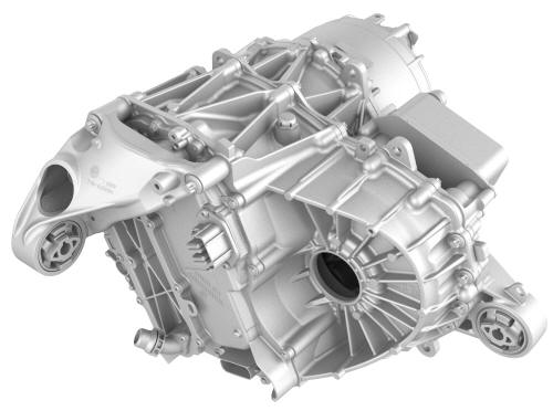
     Drive Unit - Rear (Remove and Replace)

        Remove Remove the rear drive unit from the subframe assembly. See Drive Unit - Rear (Remove and Install).

    SEE MORE:

     Harness - Charge Port to HV Battery (Three-Phase) (Remove and Replace)

    Harness - Charge Port to HV Battery (Three-Phase) - Remove     Remove Open all doors and windows. Move the driver seat and front passenger seat fully forward. Remove the 2nd row lower seat cushion. See

     Sensor - TPMS (Remove and Replace)

        Remove Remove the wheel. See Wheel (Remove and Install). Place the wheel on the tire changer, with the outside of the wheel facing up. Insert the center cl

    © 2019-2025 Copyright www.tmodel3.com