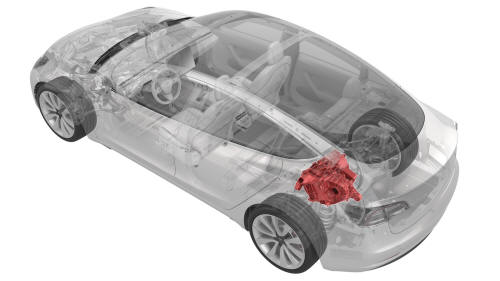
Tesla Model 3: Drive Unit - Rear (Remove and Replace)
Remove
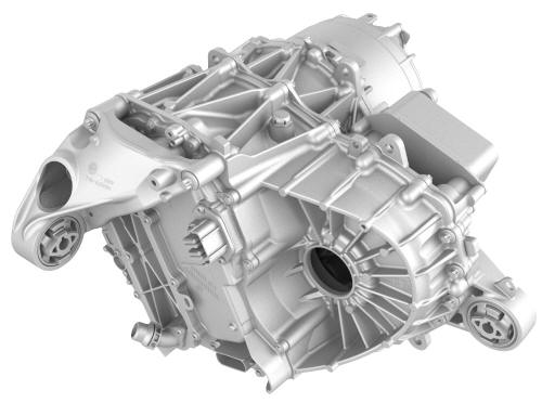
- Remove the rear drive unit from the subframe assembly. See Drive Unit - Rear (Remove and Install).
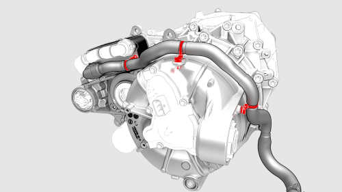
- Release the clips that attach the coolant outlet hose to the rear drive unit.
- Release the spring clip that attach the coolant outlet hose from the cooler, and then remove the hose from the rear drive unit.
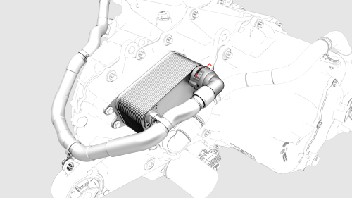
- Release the clip that attaches the inverter-to-cooler hose to the cooler, and then remove the hoses from the cooler.
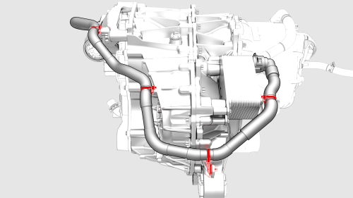
- Release the clips that attach the inverter-to-cooler hose to the rear drive unit.
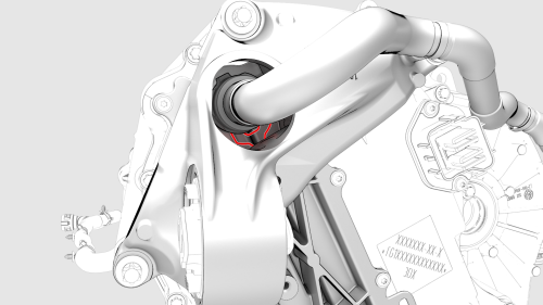
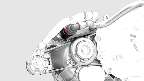
- Release the clip that attach the inverter-to-cooler
hose to the inverter, and then remove the hose.
Install
- Install the inverter-to-cooler hose to the inverter, and then attach the hose with a spring clip.
Caution: Perform a push-pull test to verify that the hose is fully seated.
- Install the clips that attach the inverter-to-coolant hose to the rear drive unit.
- Install the inverter-to-cooler hose to the cooler, and then attach the hose with spring clip.
Caution: Perform a push-pull test to verify that the hose is fully seated.
- Install the coolant outlet hose to the cooler, and then attach the hose with spring clip.
Caution: Perform a push-pull test to verify that the hose is fully seated.
- Attach the clips that hold the coolant outlet hose to the rear drive unit.
- Install the rear drive unit. See Drive Unit - Rear (Remove and Install). Note: New rear drive units come prefilled with gearbox fluid. Clean up any leaks during installation and top off the gearbox fluid as necessary.
- Install the rear subframe assembly. See Subframe Assembly - Rear (Remove and Install).
- After performing a vacuum refill of the cooling system, use Toolbox to perform the Rear Drive Unit - Remove and Replace Autodiag.
- After completing the Autodiag, continue the procedure to install the rear subframe assembly.
READ NEXT:
 Mount - Rear Drive Unit - LH (Remove and Replace)
DRAFT
Warning:
This procedure was derived from pre-production computer
models, and might not reflect the real-world situation. Warning
Motor Assembly - Rear (Remove and Replace)
Remove
Remove the rear drive unit. See Drive Unit - Rear
(Remove and Replace).
Remove the rea
SEE MORE:
Wiper Blades (Remove and Replace)
Note: This procedure was formulated
using a release candidate or production model. Follow safety requirements and
use extreme caution when working on or near high-voltage systems and components.
Remove
Use the center display to put the wipers in "Service Mode."
Release the tab that
Carrier Assembly - Charge Port (Remove and Replace)
Carrier Assembly - Charge Port - Remove
SPECIAL TOOLS
Insulation Multimeter, Fluke 1507 (NA)
(1076921-00-B)
Insulation Multimeter, Fluke 1587 (EMEA)
(1076921-00-A)
