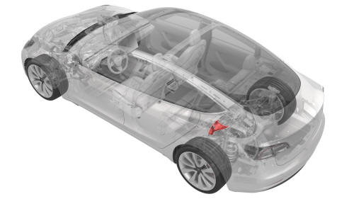
Tesla Model 3: Mount - Rear Drive Unit - LH (Remove and Replace)
Tesla Model 3 2017-2026 Service Manual / Rear Drive Unit / Rear Drive Unit Assembly / Mount - Rear Drive Unit - LH (Remove and Replace)
DRAFT
Warning: This procedure was derived from pre-production computer models, and might not reflect the real-world situation. Warnings and cautions might be missing. Follow safety requirements and use extreme caution when working on or near high voltage systems and components.Remove
- Remove the rear subframe assembly from the vehicle. See Subframe Assembly - Rear (Remove and Install).
- Support the center of the rear drive unit with rubber or wood blocks.
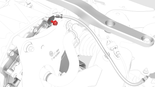
- Remove the bolt that attaches the rear drive unit ground terminal to the inverter, and remove the terminal from the inverter.
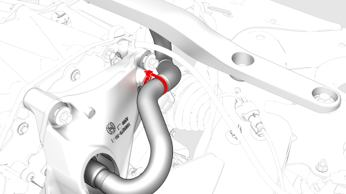
- Release the clip that attaches the coolant outlet hose to the LH mount.
- Release the clip that attaches the coolant outlet hose to the inverter fitting, and remove the hose from the inverter.
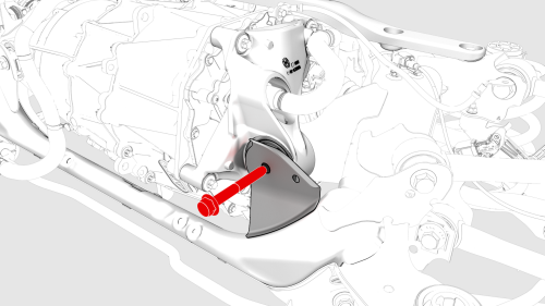
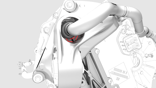
- Remove and discard the nut and bolt that attach the LH mount to the subframe.
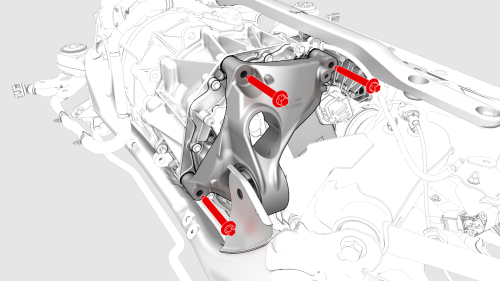
- Remove the bolts that attach the LH mount to the rear
drive unit, and remove the mount from the rear drive unit.
Install
Caution: Replace all patchbolts.Caution: Replace all nyloc nuts.
- Install the LH rear drive unit mount to the rear drive unit, and then hand-tighten the bolts (x3) that attach the mount to the rear drive unit.
- Tighten the bolts in a two-step, counter-clockwise
pattern, starting with the upper-right bolt.
 Torque 35 Nm +55 deg
- Install a new nut and bolt to attach the LH mount to the
subframe.
 Torque 80 Nm
- Connect the coolant outlet hose to the inverter fitting, and then fasten the clip that attaches the hose to the fitting.
Caution: Perform a push-pull test to verify that the hose is fully seated.
- Fasten the clip that attaches the coolant outlet hose to the LH mount.
- Install the rear drive unit ground terminal to the
inverter.
.png) Torque 10 Nm
Torque 10 Nm
- Remove the rubber or wood blocks that support the center of the rear drive unit.
- Install the rear subframe assembly into the vehicle. See Subframe Assembly - Rear (Remove and Install).
READ NEXT:
 Motor Assembly - Rear (Remove and Replace)
Remove
Remove the rear drive unit. See Drive Unit - Rear
(Remove and Replace).
Remove the rea
Sensor - Rear Motor - Speed (Remove and Replace)
Special tool required for this procedure:
1451839-00-A SKT, EP10 LOW PROFILE
1115031-00-A EXT, WOBBLE, 1/4" DR, 1.25"
SEE MORE:
SD Card - Car Computer (Remove and Replace)
Remove
Remove the 2nd row lower seat cushion. See Seat Cushion - Lower - 2nd
Row (Remove and Replace).
Remove the rear underhood apron. See Underhood Apron - Rear (Remove and
Replace).
Remove the cabin intake duct. See Duct - Cabin Intake (Remove and
Replace)
Disconnect 12V power. See 12V
Brake Pedal (Remove and Replace)
Brake Pedal - Remove
Remove
Remove the 2nd row lower seat cushion. See Seat
Cushion - Lower - 2nd Row (Remove and Replace).
Remove the rear underhood apron. See Underhood Apron
- Rear (Remove and Replace).
© 2019-2026 Copyright www.tmodel3.com
