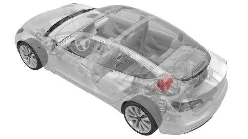
Tesla Model 3: Motor Assembly - Rear (Remove and Replace)
Remove
- Remove the rear drive unit. See Drive Unit - Rear (Remove and Replace).
- Remove the rear drive unit inverter. See Inverter - Rear Drive Unit (Remove and Install).
- Position the gearbox and motor assembly in the upright position on the service table.
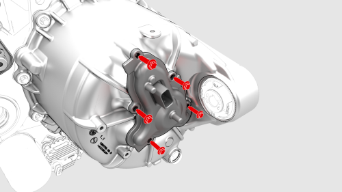
- Remove the fasteners that attach the resolver cover to the motor assembly, and then remove the resolver cover from the motor.
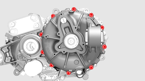
- Remove the bolts that attach the motor assembly to the gearbox assembly.
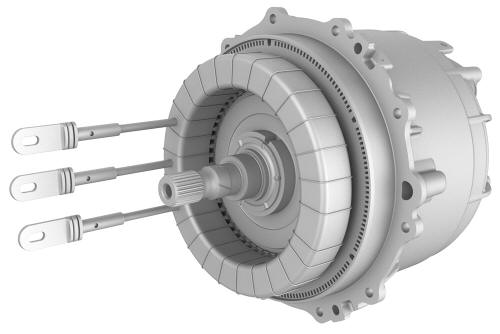
- Set up the motor sling and gantry to remove the motor assembly.
- Use the gantry to gently lift the motor assembly from the gearbox.
Tip: A trim tool can help separate the motor assembly from the gearbox should the motor assembly bind on lifting.
- Lower the motor onto the shipping crate or pallet.
- Remove the motor sling from the motor assembly.
- Remove and discard the motor assembly to gearbox
gasket.
Install
- Install a new motor assembly to gearbox gasket.
- Install new stator phase lug o-rings.
- Set up the motor sling and gantry to install the motor assembly.
- Lift the motor assembly over the gearbox for installation.
- With an assistant, align the guides and carefully lower the motor assembly into the gearbox.
Caution: Make sure to align the stator phase lug, jet ring, and inner shaft, and use a rubber hammer to gently tap the gearbox, if necessary.
- Remove the motor sling from the motor assembly.
- Install the bolts that attach the motor assembly to
the gearbox.
 Torque 15 Nm +25 deg
- Install the resolver cover on the motor assembly,
and install the bolts that attach the resolver cover to
the motor assembly.
 Torque 15 Nm +25 deg
Caution: Make sure to align the brush and motor.
- Install the rear drive unit inverter. See Inverter - Rear Drive Unit (Remove and Install).
- Install the rear drive unit. See Drive Unit - Rear (Remove and Replace).
READ NEXT:
 Sensor - Rear Motor - Speed (Remove and Replace)
Special tool required for this procedure:
1451839-00-A SKT, EP10 LOW PROFILE
1115031-00-A EXT, WOBBLE, 1/4" DR, 1.25"
HV Header - Inverter - Rear Drive Unit (Remove
and Replace)
HV Header - Inverter - Rear Drive Unit - Remove
SPECIAL TOOLS
Extractor, Drive Unit HV Header, Model 3
(1142608-00-B)
SEE MORE:
Skid Plate - HV Battery - Rear (Remove and Replace)
DRAFT
Warning:
This procedure was derived from pre-production computer models, and
might not reflect the real-world situation. Warnings and cautions might be
missing. Follow safety requirements and use extreme caution when working on or
near high voltage systems and components.
Do not redistri
Compressor (Remove and Replace)
Compressor- Remove
Warning:
Only technicians who have been trained in High Voltage Awareness are
permitted to perform this procedure. Proper personal protective equipment (PPE)
and insulating HV gloves with a minimum rating of class 0 (1000V) must be worn
at all times a high voltage cable, bus
