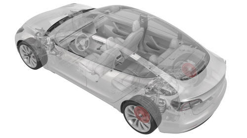
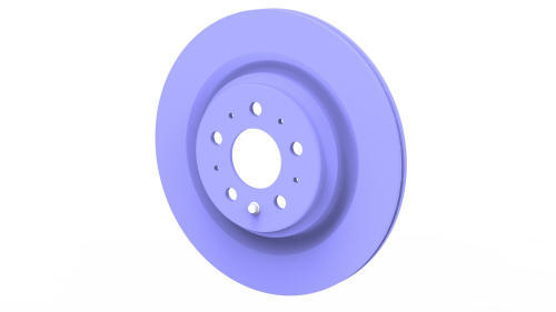
Tesla Model 3: Brake Rotor - Rear - LH (Remove and Replace)
Tesla Model 3 2017-2026 Service Manual / Brakes / Brake Discs and Calipers / Brake Rotor - Rear - LH (Remove and Replace)
SPECIAL TOOLS
Tool, Caliper Spreader, Model 3 (1134786-00-A)
Remove
- Raise the vehicle and remove the LH rear wheel. See Wheel (Remove and Install).
- Use Toolbox to place the vehicle into EPB Service Mode. See Release Parking Brake Using Toolbox
.jpg)
- Disconnect the electrical wiring harness connector from the parking brake.
.jpg)
- Remove and discard the bolts that attach the LH rear caliper to the LH
rear knuckle, remove the caliper from the knuckle, and allow the caliper to
hang from an S-hook.
.jpg) Torque 83 Nm
Torque 83 Nm - Use the caliper spreader tool to push the caliper pistons to the fully open position.
.jpg)
- Remove the bolt that attaches the brake rotor to the hub, and then
remove the brake rotor from the hub.
.jpg) Torque 5 Nm
Torque 5 Nm
Install
Installation procedure is the reverse of removal, except for the following:
- Replace all patchbolts.
- Press the brake pedal at least 5 times to seat the pads against the rotor.
Warning: Always check that the brake pads are seated correctly before driving the vehicle.
READ NEXT:
 Shield - Dust - Brake - Front - LH (Remove and Replace)
Remove
Note: This procedure is applicable to both Model 3 base and sport
brake dust shields.
Remove the LH front brake rotor. See
Brake Rotor - Front - LH (Remove and Replace).
Remove the b
Shield - Dust - Brake - Rear - LH (Remove and Replace)
Shield - Dust - Brake - Rear - LH - Remove
SPECIAL TOOLS
Card, Magnetic Field Viewer (1062500-00-A)
SEE MORE:
Brake Pedal (Remove and Replace)
Brake Pedal - Remove
Remove
Remove the 2nd row lower seat cushion. See Seat
Cushion - Lower - 2nd Row (Remove and Replace).
Remove the rear underhood apron. See Underhood Apron
- Rear (Remove and Replace).
Cover - HV Probe - HV Battery (Remove and Replace)
Warning:
Only technicians who have been trained in High Voltage Awareness are
permitted to perform this procedure. Proper personal protective equipment (PPE)
and insulating HV gloves with a minimum rating of class 0 (1000V) must be worn
at all times a high voltage cable, busbar, or fitting is ha
© 2019-2026 Copyright www.tmodel3.com
