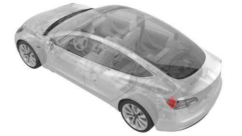
Tesla Model 3: Carrier Assembly - Charge Port - Remove
SPECIAL TOOLS
Insulation Multimeter, Fluke 1507 (NA) (1076921-00-B)
Insulation Multimeter, Fluke 1587 (EMEA) (1076921-00-A)
Insulation Multimeter, Fluke 1508 (APAC) (1076921-01-B)
Test Probes, Slim, Fluke TP38 (1130480-00-A)
Warning:Only technicians who have been trained in High Voltage Awareness are permitted to perform this procedure. Proper personal protective equipment (PPE) and insulating HV gloves with a minimum rating of class 0 (1000V) must be worn at all times a high voltage cable, busbar, or fitting is handled. Refer to Tech Note TN-15-92-003, "High Voltage Awareness Care Points" for additional safety information.
Warning: Remove all jewelry (watches, bracelets, rings, necklaces, earrings, ID tags, piercings, etc.) from your person, and all objects (keys, coins, pens, pencils, tools, fasteners, etc.) from your pockets before performing any procedure that exposes you to high voltage.
Warning: Proper personal protective equipment (PPE) is required to perform this procedure:
- High voltage insulating gloves
- Leather glove protectors
- High voltage glove tester
- Safety glasses
- Electrical hazard rated safety shoes
A glove inflator is the only recommended way to test HV gloves. Both HV gloves must pass testing before beginning this procedure. If either glove does not pass the air check, discard the pair.
Warning: Make sure that the HV gloves are not expired. HV gloves can be used up to 12 months after the testing date printed on the glove, but only 6 months after first use even if the gloves are still within the 12-month period.
Remove
- Perform the charge port voltage check procedure. See Charge Port Voltage Check.
- Remove the LH rear sill panel trim. See Trim - Sill Panel - Rear - LH (Remove and Replace).
- Remove the LH trunk side trim. See Trim - Side - Trunk - LH (Remove and Replace).
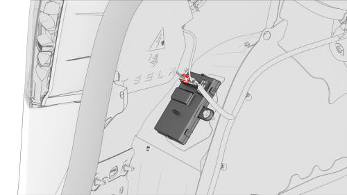
- Disconnect the low voltage charge port connector from the charge port ECU.
- Release the clip that attaches the low voltage electrical wiring harness to the charge port closeout panel.
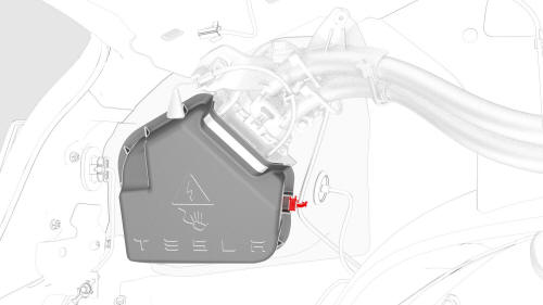
- Release the tabs around the charge port closeout panel, and then remove the panel from the vehicle.
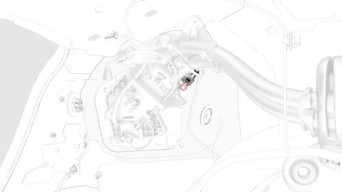
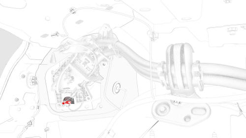
- Remove the bolt that attaches the charge port electrical ground to the body.
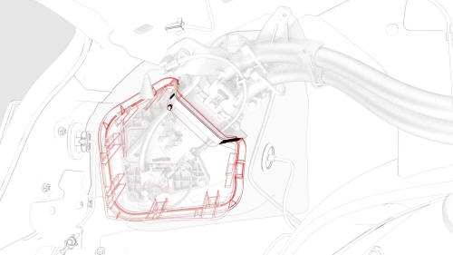
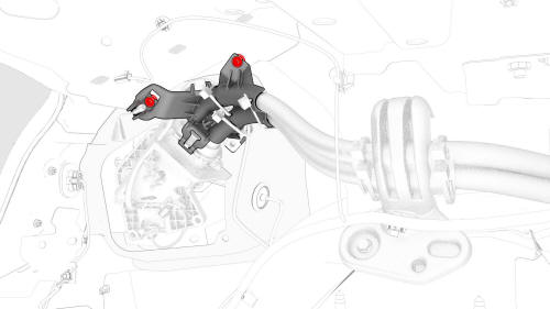
- Remove the bolts that attach the charge port assembly to the body.
- Release the clips that attach the charge port electrical harness to the body.
Note: Pull the charge port away from the body for access.
- Remove the release arm from the latch actuator.
Note: Note the orientation of the release arm before removing it from the latch actuator.
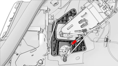
- Release the latch cable from the locking tabs on the charge port assembly.

- Disconnect the electrical connector from the latch actuator.
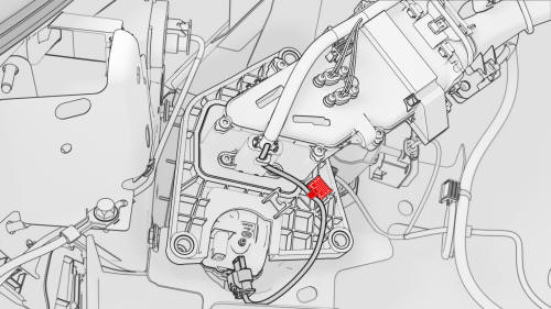
- Release the clip that attaches the actuator harness to the charge port assembly, and then carefully cut the clip off of the harness.
Note: Note the location of the clip before cutting it off.
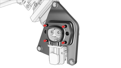
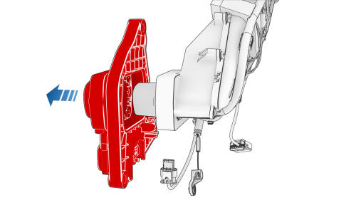
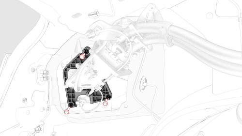
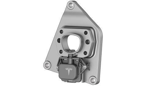
- Remove the bolts that attach the carrier assembly to the charge port assembly, and then remove the carrier assembly.
Note: The carrier and latch actuator are removed
together.
READ NEXT:
 Carrier Assembly - Charge Port - Install
Install
Position the new carrier assembly on the charge port
as
Charge Port - Manual Release of Cable
DRAFT
Warning:
This procedure was derived from pre-production computer models, and
might not reflect the real-world situation. Warnings and cautions might be
missing. Follow safety requirements a
SEE MORE:
About Dashcam
Note: Dashcam is a BETA feature.
In addition to supporting Autopilot features, the cameras can record and store video footage on a USB flash drive. This can be convenient in situations where you want a video recording of a particular incident, such as a collision. You can pause, resume, or save vid
Door - Rear - LH (Install)
Make sure that the upper bolt for each door hinge is installed, and the
bolt head extends approximately 10 mm from flush.
With assistance, lower the rear LH door onto the door hinges, and engage
the upper bolts into the hinges.
Install the lower bolt of each hinge into the door
