Tesla Model 3: Forward Facing (Target Calibration)
.jpg)
SPECIAL TOOLS
Camera Calibration Target (1053066-00-A)
Wrench, 2.5mm, Thin (1448868-00-A)
Note: This procedure describes how to calibrate the forward facing cameras. It does not apply to the rear facing camera.
Setup
- Park the vehicle on a flat surface with at least 106 cm (3.5 ft) of space in front of the front fascia.
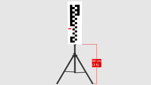
- Place the target in the appropriate starting position:
- The bottom of the target is 90 cm (3 ft) from the ground.
- The checkered portion of the target is facing towards the vehicle.
- The target is centered with the Tesla "T" on the hood.
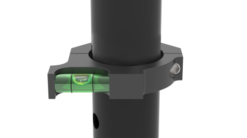
- Make sure that the target is on flat ground by examining the bubble level on the back of the target.
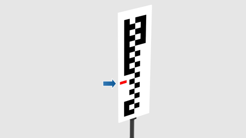
- Apply a piece of red tape on the target referencing camera height; top of tape should be target height of 128 cm from the ground.
Calibrate
Note: Calibration of the forward facing camera is an iterative process. That is, check the narrow and main images, adjust accordingly, check the narrow and main images, adjust accordingly, etc.
Note: The actions of entering the vehicle, inserting the wrench, turning the wrench, and then exiting the vehicle affect the camera alignment during those actions, therefore you cannot adjust the camera in real time.
- Remove the rear view mirror trim. See Quad Camera Cover - Lower (Remove and Replace).
- Connect a laptop with Toolbox to the vehicle.
- Exit the vehicle and select Dashboards > Service Tools > DAS Image Capture > Pre-Calibration.
Caution:
Freeze-frame narrow and main images are captured, and the vehicle needs to be unoccupied at this time in order for the ride height to maintain specification
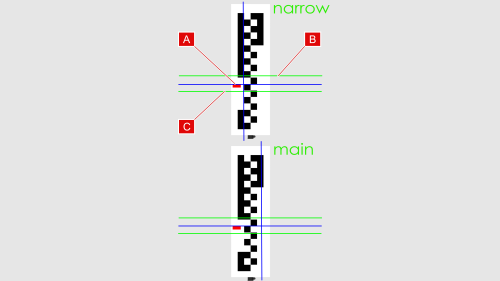
- Review the freeze-frame narrow and main images:
Note: The upper green line (B) indicates a -2.0 degrees pitch. The lower green line (C) indicates a +1.5 degree pitch. Ideally, the top of the red tape (A) should coincide with the blue horizontal line. However, if the top of the red tape is between the green lines, that is sufficient.
- If the top of the red tape (A) is between the two green lines (B and C), the forward facing camera is within calibration. Go to step 8.
- If the top of the red tape (A) is not between the two green lines (B and C), the forward facing camera needs adjustment. Continue to the next step to adjust the camera.
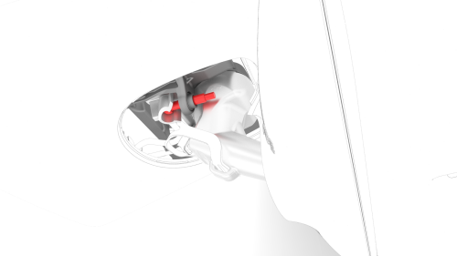
- Use a pitch adjustment wrench to adjust the camera pitch so that the top of the red tape will be between the 2 green lines.
Note: Rotating the pitch adjustment wrench counterclockwise will move the red tape up. Rotating the pitch adjustment wrench clockwise will move the red tape down. 1 full rotation of the pitch adjustment wrench changes the pitch by approximately 1 degree.
- Exit the vehicle, and in Toolbox, select Capture Image to capture updated freeze-frame narrow and main images.
Note: Make sure that the vehicle remains unoccupied as the image capture is performed.
- Repeat the procedure from step 4.
- Install the rear view mirror trim. See Quad Camera Cover - Lower (Remove and Replace).
- Disconnect the laptop from the vehicle.
- Remove the target from the front of the vehicle.
- The vehicle needs to be driven by the customer to complete the calibration procedure.
Note: DAS functions will be unavailable until the calibration has completed.
READ NEXT:
 Interior Camera
Camera - Occupant (Remove and Replace)
Remove
Remove the rear view mirror. See Mirror - Rear View (Remove and Replace).
Release the clips that attach the upper quad camera cover, disconnect
Rear Cameras
Camera - Rear Facing (Remove and Replace)
Remove
Remove the trunk trim. See Trim - Lid - Trunk (Remove and Replace).
Remove the trunk exterior release switch. See Switch - Exterior Release
- Tr
SEE MORE:
Seal - Inner Belt - Front Door - LH (Remove and Replace)
Remove
Remove the LH front door trim panel. See
Panel - Door Trim - Front - LH (Remove and Replace).
Remove the rear of the inner belt seal from the door.
Release the rest of the seal from the door, and then remove the seal
from the door.
Install
Installation procedure is the rever
Switch - Exterior Release - Trunk (Remove and Replace)
Remove
Remove the trunk lid trim. See Trim - Lid - Trunk (Remove and Replace).
Disconnect the electrical connectors from the trunk exterior release
switch and the rear facing camera.
Remove the bolts that attach the rear facing camera to the trunk
exterior release switch, and
