
Tesla Model 3: Isolator - Motor Mount - Front - LH (Remove and Replace)
Tesla Model 3 2017-2026 Service Manual / Chassis / Isolator - Motor Mount - Front - LH (Remove and Replace)
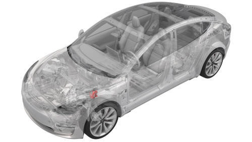
Remove
- Remove the front subframe assembly from the vehicle. See Subframe Assembly - Front (Dual Motor) (Remove and Install).
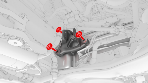
- Remove and discard the bolts that attach the LH front motor mount isolator to the body, and then remove the isolator from the vehicle.
Warning: Secure the LH front motor mount isolator while removing the
bolts, as the isolator will fall once unbolted.
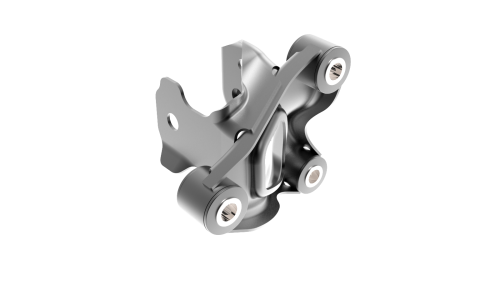
Install
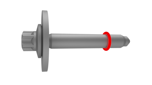
- Install an o-ring (part number 1473485-00-A) 5 threads from the tip of each new bolt (x3).
- Hand-tighten the new bolts that attach the LH front motor mount isolator to the body.
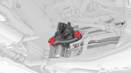
- Tighten the new bolts (x3) that attach the LH front motor mount isolator
to the body.
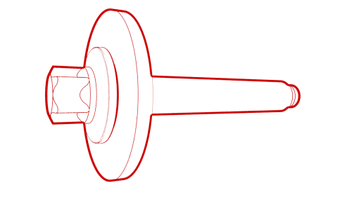 Torque 62 Nm
 - Install the front subframe assembly on the vehicle. See Subframe Assembly - Front (Dual Motor) (Remove and Install).
READ NEXT:
 Subframe Assembly - Front (RWD) - Remove
SPECIAL TOOLS
Tool, Axle Extraction, Model 3 (1133386-00-A)
Fixture, Subframe, Model 3 (1099645-00-C)
OTC Lift, 1,650LB Powertrain Table (1066521-00-A)
Lifting Sling, Drive Unit, Model 3 (NA, APAC)
Subframe Assembly - Front (RWD) - Install
Install
Position the subframe lifting tool against the front subframe, and then
attach the straps (x3) to the subframe.
Note: Make sure to align the two subframe lifting tool guides with
the fro
SEE MORE:
Footrest - Driver (Remove and Replace)
Remove
Open the LH front door.
Move the driver seat fully to the rear.
Release the clips that attach the driver footrest to the body, and
remove the footrest from the vehicle.
Install
Installation procedure is the reverse of removal.
Charge Port - Manual Release of Cable
DRAFT
Warning:
This procedure was derived from pre-production computer models, and
might not reflect the real-world situation. Warnings and cautions might be
missing. Follow safety requirements and use extreme caution when working on or
near high voltage systems and components
Procedure
Ensu
© 2019-2026 Copyright www.tmodel3.com
