Tesla Model 3: Subframe Assembly - Front (RWD) - Remove
SPECIAL TOOLS
Tool, Axle Extraction, Model 3 (1133386-00-A)
Fixture, Subframe, Model 3 (1099645-00-C)
OTC Lift, 1,650LB Powertrain Table (1066521-00-A)
Lifting Sling, Drive Unit, Model 3 (NA, APAC) (1130279-00-A)
Lifting Sling, Drive Unit, Model 3 (EMEA) (1130279-01-A)
Caution:
Vehicles built before March 25th, 2019 have 1st generation front subframes. Vehicles built on March 25th, 2019 and after have 2nd generation front subframes. When a 1st generation subframe is replaced with a 2nd generation subframe, the 1st generation (discontinued) steering rack, if installed, must be replaced with a 2nd generation (currently available) steering rack. Refer to the Electronic Parts Catalog for the latest information.
Remove
- Remove the front subframe assembly from the vehicle. See Subframe Assembly - Front (Dual Motor) (Remove and Install).
- Remove the steering rack. See Steering Rack (Dual Motor) (Remove and Replace).
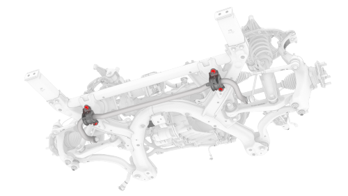
- With an assistant, remove and discard the nuts that attach the front stabilizer bar to the front subframe, and then remove the stabilizer bar from the subframe.
.png)
- Remove the bolts that attach LH and RH crash can brackets to the front subframe, and then set the crash can brackets aside.
- Install an axle extraction tool between the front drive unit and the inner joint of the LH front drive unit halfshaft, and then strike the end of the extraction tool with a dead blow hammer to unseat the halfshaft.
- With assistance, remove the LH front drive unit halfshaft from the front drive unit.
- Repeat steps 5 to 6 on the RH front drive unit halfshaft.
.png)
- Release the locking tab, and then push the handle downward to disconnect the front drive unit inverter logic connector.
.png)
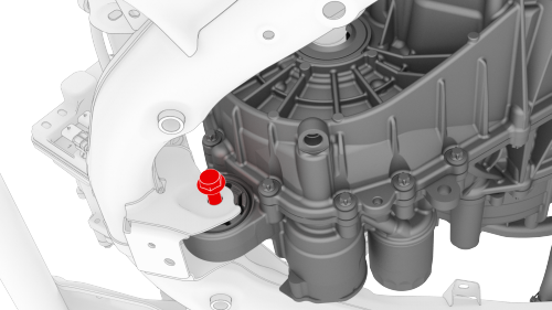
- Release the red locking tab, and then press down on the tab to disconnect the resolver logic connector.
.png)
- Release the grey locking tab, and then press down on the tab to disconnect the oil pump connector.
.png)
- Release the clip that attaches the front drive unit harness to the front drive unit motor.
.png)
- Release the clips that attach the front drive unit harness to the front subframe.
.png)
- Release the clips that attach the front drive unit harness to the front drive unit inverter.
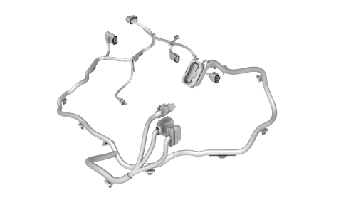
- Remove the front drive unit harness from the front subframe.
- Position the subframe assembly under the gantry.
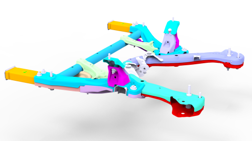
- Install the drive unit sling onto the gantry hook.
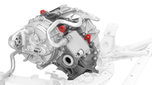
Front drive unit sling hook locations
- Install the drive unit sling hooks onto the front drive unit.
- Slightly raise the gantry hook until the drive unit sling is taut.
- Remove the bolt that attaches the front drive unit to the front subframe.
- Lift the front drive unit up and away from the front subframe.
Note: Make sure not to move the rear front drive unit support posts.
- Release the straps that attach the front subframe to the subframe lifting tool.
- Remove the front subframe from the subframe lifting tool.
READ NEXT:
 Subframe Assembly - Front (RWD) - Install
Install
Position the subframe lifting tool against the front subframe, and then
attach the straps (x3) to the subframe.
Note: Make sure to align the two subframe lifting tool guides with
the fro
Subframe Assembly - Front (RWD) (Remove and Replace)
Caution:
Vehicles built before March 25th, 2019 have 1st generation front
subframes. Vehicles built on March 25th, 2019 and after have 2nd generation
front subframes. When a 1st generation subfra
SEE MORE:
Speaker - Emergency (Remove and Replace)
Remove
Remove the RH footwell cover. See Cover - Footwell - Passenger (LHD) (Remove
and Replace).
Disconnect the electrical connector for the emergency speaker.
Release the screws that attach the emergency speaker to the RH footwell
cover, and then remove the emergency speaker.
Bushing - Rear Drive Unit - RH (Remove and Replace)
SPECIAL TOOLS
Kit, Drive Unit Bushing R&R, Model 3
(1137785-00-A)
Remove
Remove the rear drive unit. See Drive Unit -
Rear (Remove and Install)
