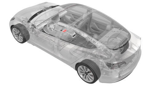
Tesla Model 3: Module - Body Controller - Security (Remove and Replace)
Module - Body Controller - Security- Remove
Remove
- Open all doors and lower all windows
- Remove the 2nd row lower seat cushion. See
Seat Cushion - Lower - 2nd Row (Remove and Replace).
- Move the driver seat and front passenger seat fully rearward.
- Disconnect 12V power. See
12V Power (Disconnect and Connect).
- Open the armrest.
- Remove the LH and RH center console decor trims. See
Decor Trim - Center Console (Remove and Replace).
.png) <>
<>
LH shown, RH similar
- Remove the screws and release the tabs that attach the LH bright strip
to the center console, and then remove the strip from the console. Repeat
this step to remove the RH bright strip.
.jpg)
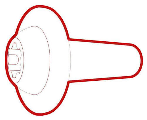
- Release the clips (x6) that attach the cup holder decor panel to the cup
holder assembly, and then separate the cup holder decor panel from the
center console assembly.
.jpg)
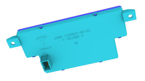
- Disconnect the electrical connector from the security body controller
module, and then remove the cup holder decor panel from the vehicle.
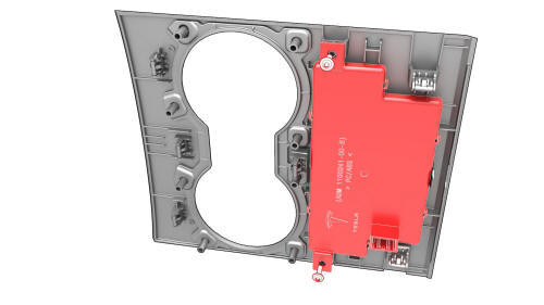
- Remove the screws that attach the security body controller module to the
cup holder decor panel, and then remove the security body controller module
from the panel.
Module - Body Controller - Security- Install
Install
- Install the screws (x2) that attach the security body controller module
to the cup holder decor panel.
 Torque 1.6 Nm
- Connect the electrical connector to the security body controller module.
- Attach the clips (x6) that attach the cup holder decor panel to the
center console assembly.
- Install the RH bright strips: Start with the corner nearest to the IP
carrier, and then continue towards the rear. Repeat this step on the LH
bright strip.
LH shown, RH similar
- Install the screws (x7) that attach the RH bright strip to the center
console assembly. Repeat this step on the LH bright strip.
.jpg) Torque 1.6 Nm
Torque 1.6 Nm
- Install the RH center console decor trim, and then repeat this step on
the LH center console decor trim. See
Decor Trim - Center Console (Remove and Replace).
- Reconnect 12V power, but do not install the rear underhood apron at this
time. See
12V Power (Disconnect and Connect).
- Connect a laptop with Toolbox to the vehicle.
- In Toolbox, type "VCSEC" in the search tab.
Note: Make sure "Actions" is selected, if not already.
- In Toolbox, click the play button next to the "PING-TP_VCSEC" and select
Run.
Note: This action will ensure communication with the newly
installed VCSEC.
- Use Toolbox to update the vehicle firmware.
- Log into Garage using the laptop, and then search for the VIN or vehicle
nickname.
- From the SUMMARY tab, click Delete VCSEC Certificate, and then click OK
on the pop up window.
Caution:
This action CANNOT be undone.
Note: This action will remove associated VCSEC certificate from the
server.
- In Toolbox, click the play button next to "PROC_VCSEC_X_PROVISIONING"
and select Run.
Note: This action secures VCSEC by exchanging encryption
keys and certificate with Tesla and the vehicle.
Note: Customer's phone will need to be re-paired to the vehicle
after completing this entire procedure.
- In Toolbox, click the play button next to "TEST-SELF_VCSEC_X_ENDPOINT-COMM"
and select Run.
Note: This action checks endpoint communication ability.
- In Toolbox, click the play button next to "repair_network.ODIN_VCSEC_pairNFCCard"
and select Run.
- Put the NFC key cards on the center console behind the cup holders.
Note: 2 NFC key cards are required when pairing, either 2
NFC key cards that have never been programmed, or one programmed NFC key card
and one that has never been programmed.
- In Toolbox, type the number of key cards to be paired to the vehicle,
and then select Run Network.
- In Toolbox, select the environment/garage type for the vehicle.
Note: If the routine fails, select retry.
- Check the function of the new programmed NFC card keys: Tap each of the
NFC key cards on the LH exterior B-pillar area to lock and unlock the
vehicle, and then put one NFC key card at a time on the center console
behind the cup holders and step on the brake pedal to start the vehicle.
- In Toolbox, type "IMMOBILIZER" in the search tab.
- In Toolbox, click the play button next to "PROC_DI_X-IMMOBILIZER" and
select Run.
Note: This action will pair new VCSEC with DI to the
initialize the immobilizer.
- In Toolbox, type "ODOMETER" in the search tab.
- In Toolbox, click the play button next to "PROC-DID_DI_VEHICLE-ODOMETER"
and select Run.
- In Toolbox, type "RESET_DI" in the search tab.
- In Toolbox, click the play button next to "TEST-RESET_DI" and select
Run.
Note: This action runs a routine to clear alerts.
Note: Make sure to select routine for "DI UDS ECU Reset."
- Disconnect the laptop from the vehicle.
- Install the rear underhood apron. See
Underhood Apron - Rear (Remove and Replace).
- Close the hood.
- Move the driver seat and front passenger seat fully forward.
- Install the 2nd row lower seat cushion. See
Seat Cushion - Lower - 2nd Row (Remove and Replace).
- Restore the driver seat and front passenger seat back to their original
position.
READ NEXT:
Remove
Remove the front fascia assembly. See
Fascia - Front (Remove and Install).
Disconnect the connector from the battery backed siren.
Remove the bolt that attaches the battery backe
SEE MORE:
HV Battery (RWD) (Remove and Install) - Remove
SPECIAL TOOLS
Adapter, Lift Pad, Model 3 (1453419-00-A)
Key, Seat Belt Release, Model 3 (1133787-00-A)
ASY, Battery Table, Manual Lift (1020566-00-F)
Top Plate, Battery Table, Manual Lift (1020566-99-A)
Hoist, H-Frame EMEA (1129166-00-A)
Kit, Alignment
Remove
Remove the 2nd row LH seat back assembly. See
Seat Back - 2nd Row - LH (Remove and Install).
Release the tabs that attach the pivot sleeve to the seat back assembly
pivot pin, and then remove the sleeve from the pin.
 Siren - Battery Backed (Remove and Replace)
