Tesla Model 3: Module - Body Controller - RH - Install
Install
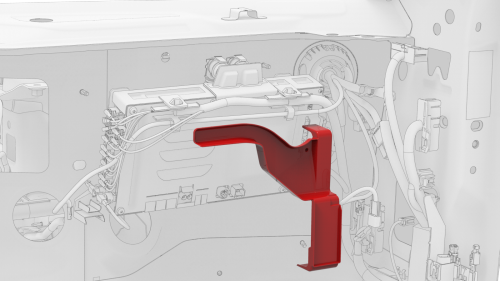
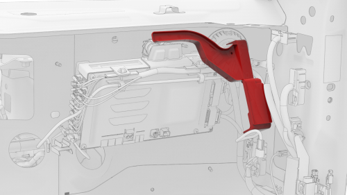
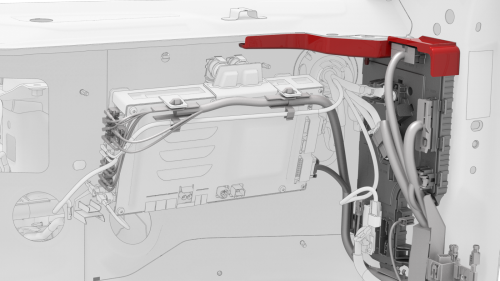
- Position the shroud by itself in position on the vehicle.
Note: Position the shroud vertical and move it up above the computer, and then pivot the lower edge so that the shroud sits horizontally.
- Maneuver the RH body controller module into position under the IP carrier, and then install the 2 clips that attach the shroud to the module.
Note: Make sure that both clips are fully seated.
- Align the W-clip with the body cutout, and then slide down to attach the RH body controller to the body.
.png)
- Install new nut that attaches the RH body controller to the body.
.png)
- Install the clip that attaches the wiring harness to the RH body controller.
.png)
- Move the RH body harness towards the right side of the RH body controller, and then install attach the harness clips (x4) to the RH body controller.
.png)
- Install the clip that attaches the RH body harness at the lower A-pillar area.
- Connect the wiring harnesses at the RH lower A-pillar clip.
.png)
- Connect the body 3 electrical connector onto the RH body controller module.
Note: Make sure that the body 3 electrical connector lock is fully engaged.
.png)
- Connect the body 1 electrical connector onto the RH body controller module.
Note: Make sure that the body 1 electrical connector lock is fully engaged.
- Connect the body 2 electrical connector onto the RH body controller module.
Note: Make sure that the body 2 electrical connector lock is fully engaged.
- Install the harness clips (x2) onto the lower IP carrier.
.png)
- Install new nuts (x2) that attach the positive cables onto the RH body controller module.
.png)
- Connect the inline electrical connector, and then attach it to the RH body controller module.
.png)
- Connect the front wiring harness electrical connector onto the RH body controller module.
.png)
- Connect the HVAC electrical connector onto the RH body controller module.
.png)
- Connect the instrument panel electrical connector onto the RH body controller module.
.png)
- Connect the instrument panel harness coaxial cable onto the RH body controller module.
.png)
- Connect the front passenger seat electrical connector onto the RH body controller module.
Note: Make sure that the front passenger seat electrical connector lock is fully engaged.
.png)
- Connect the RH front door electrical connector onto the RH body controller module.
Note: Make sure that the RH front door electrical connector lock is fully engaged.
.png)
- Connect the RH front door wiring connectors onto the RH body controller module.
.png)
- Install the nuts that attach the RH carpet locator bracket onto the vehicle. Torque 2.5 Nm
- Fold the RH front carpet back to its original position.
.png)
- Install the clips that attach the RH front carpet to the footwell area.
- Install the RH center console side panel carpet. See Carpet - Side Panel - Center Console - LH (Remove and Replace).
- Install the RH front floor mat.
- Install the glove box. See Glove Box (LHD) (Remove and Replace).
- Install the front passenger knee airbag. See Airbag - Knee - Front Passenger (Remove and Replace).
- Install the passenger footwell cover. See Cover - Footwell - Passenger (LHD) (Remove and Replace).
- Install the RH lower A-pillar trim. See Trim - A-Pillar - Lower - LH (Remove and Replace).
- Install the RH middle A-pillar trim. See Trim - A-Pillar - Middle - LH (Remove and Replace).
- Install the main instrument panel decor trim. See Decor Trim - Instrument Panel - Main (Remove and Replace).
- Install the RH air wave end cap. See End Cap - Air Wave - LH (Remove and Replace).
- Install the RH instrument panel end cap. See End Cap - Instrument Panel - LH (Remove and Replace).
- Install the LH air wave end cap. See End Cap - Air Wave - LH (Remove and Replace).
- Install the LH air wave end cap. See End Cap - Air Wave - LH (Remove and Replace).
- Connect 12V power. See 12V Power (Disconnect and Connect).
Caution: Do not power on the climate control system until the firmware has been updated, the seat and window calibration has been performed, and this procedure has been fully completed.
- Install the rear underhood apron. See Underhood Apron - Rear (Remove and Replace).
- Install the 2nd row lower seat cushion. See Seat Cushion - Lower - 2nd Row (Remove and Replace).
- Update the vehicle firmware.
- Connect a laptop with Toolbox to the vehicle.
- Using Toolbox, type Seat in the search field.
Note: Make sure that Actions is selected in Toolbox, if not already.
- Using Toolbox, click the play button next to PROC_VCRIGHT_SEAT-CALIBRATE, and then select Run.
- Using Toolbox, type Window in the search field.
Note: Make sure that Actions is selected in Toolbox, if not already.
- Using Toolbox, click the play button next to PROC_VCLEFT-VCRIGHT_ X_WINDOW-CALIBRATION, and then select Run.
- Disconnect the laptop from the vehicle.
READ NEXT:
 Module - HomeLink Transmitter (Remove and Replace)
Remove
Remove the front fascia. See Fascia - Front (Remove and Install).
Disconnect the electrical connector from the HomeLink transmitter module.
Release the tab, and then slide the H
Sensor - Radar - Front (Calibration)
Calibrate
Perform a 4-wheel alignment. See Four Wheel Alignment (Check and Adjust).
Connect a laptop with Toolbox to the vehicle.
With an assistant, use Toolbox to perform a radar drive cycle
SEE MORE:
Procedure (Three-Phase) (Except China)
Open the charge port door.
Disconnect 12V power. See 12V Power (Disconnect and
Connect).
Set the insulation multimeter to measure the DC
voltage across the 12V auxiliary battery terminals.
Caution:
If the voltage across the 12V auxiliary
Bracket - Hinge - Seat Back - 2nd Row - LH (Remove and Replace)
Remove
Remove the 2nd row lower seat cushion. See
Seat Cushion - Lower - 2nd Row (Remove and Replace).
Remove the LH 2nd row seat side bolster. See
Bolster - Side - Seat - 2nd Row - LH (Remove and Replace).
Remove the LH 2nd row seat back. See
Seat Back - 2nd Row - LH (Remove and Install).
