Tesla Model 3: Oil Pump - Front Drive Unit - Install
Tesla Model 3 2017-2024 Service Manual / Front Drive Unit / Front Gearbox and Halfshafts / Oil Pump - Front Drive Unit (Remove and Replace) / Oil Pump - Front Drive Unit - Install
Install
Installation procedure is the reverse of removal, except for the following:- Lubricate the front drive unit oil pump o-rings with ATF-9.
- Use Toolbox to update the vehicle firmware.
- Lightly coat the oil pump O-rings with clean ATF-9 fluid.
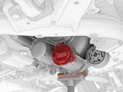
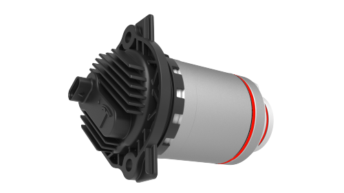
- Install the oil pump into the front drive unit.
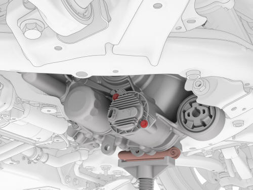
- Install the bolts that attach the oil pump to the front drive unit. Torque 5 Nm + 20 degrees
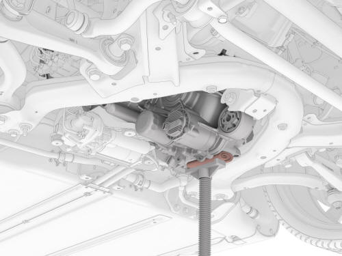
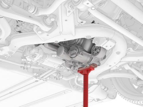
- Carefully raise the front underhoist stand until the front drive unit front bushing aligns with the front subframe mount.
.png)
- Install the bolt that attaches the front drive unit
to the front subframe.
.png) Torque 80 Nm
Torque 80 Nm
- Remove the underhoist stand and shop towel from the LH side of the front drive unit.
- Refill the front drive unit gearbox fluid. See Gearbox Fluid - Front Drive Unit (Drain and Refill).
- Install the front aero shield panel. See Panel - Aero Shield - Front (Remove and Replace).
- Connect 12V power. See 12V Power (Disconnect and Connect).
- Use Toolbox to update the vehicle firmware.
READ NEXT:
 Oil Screen - Front Drive Unit (Remove and Replace)
SPECIAL TOOLS
KIT, DRIVE UNIT OIL DRAIN, MODEL 3 (1134264-00-A)
KIT, DRIVE UNIT OIL FILL, MODEL 3 (1139126-00-A)
Tool, DUF Dipstick, Model 3 (1446276-20-A)
SWITCHBOX, OIL PUMP, MODEL 3 (1131264-00-A
Seal - Oil - Differential to Halfshaft - Front Drive Unit - LH (Remove and
Replace)
SPECIAL TOOLS
Tool, Axle Extraction, Model 3 (1133386-00-A)
Tool, Hub Puller, Hydraulic (1096075-00-A)
Install Tool, Output Seal, Model 3 (1131206-00-A)
Tool, Seal Puller, Adjustable (1052583-00-A)
SEE MORE:
AC charging interruptedCheck
power source or charging
equipment(CP_a055)
Charging stopped because communication
between the vehicle and the external charging
equipment was interrupted.
Confirm whether the external charging
equipment is powered by looking for any
status lights, displays, or other indicators on
the equipment.
If the equipment is not powered, try
HV Header - HV Battery- Install
Install
Install the HV header onto the HV battery.
Note: Push and pull on the header to make sure it is secured.
Install and hand-tighten the bolts that attach the HV header to the HV
battery
Tighten the bolts to proper torque.
Torque 10 Nm
Fully raise the handle on the rear dr
© 2019-2024 Copyright www.tmodel3.com
