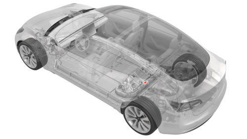
Tesla Model 3: Shunt - HV Battery (Remove and Replace)
SPECIAL TOOLS
Ratchet, 1/4" Sq Dr, HV Insulated (1057602-00-A)
Ext Bar, Wobble, 1/4" Dr, HV Insulated (1057603-00-A)
Skt, 1/4" Sq Dr, 13mm, HV Insulated (1057606-00-A)
Resistance meter, microohm, Hioki RM 3548 (1076927-00-A)
Warning: Only technicians who have been trained in High Voltage Awareness are permitted to perform this procedure. Proper personal protective equipment (PPE) and insulating HV gloves with a minimum rating of class 0 (1000V) must be worn at all times a high voltage cable, busbar, or fitting is handled. Refer to Tech Note TN-15-92-003, "High Voltage Awareness Care Points" for additional safety information.
Remove
- Remove the pyrotechnic battery disconnect. See Pyrotechnic Battery Disconnect (Remove and Replace).
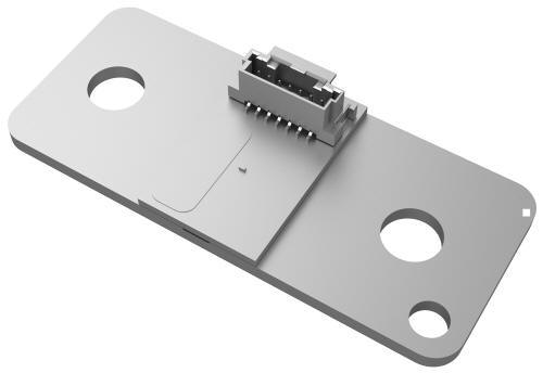
- Disconnect the electrical harness from the shunt connector
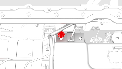
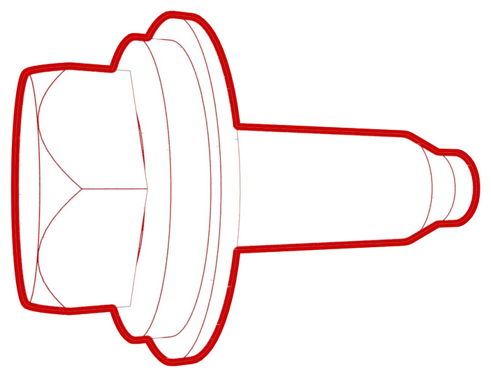
- Remove and discard the bolt that attaches the shunt to the busbar.
- Remove the shunt from the vehicle.
Install
- Use an IPA wipe to clean the HV mating surfaces of the shunt, busbar, and the pryotechnic battery disconnect.
- Install the shunt to the busbar, install a new bolt to attach the shunt
to the busbar, and then mark the bolt with a paint pen after it is torqued.
 Torque 9 Nm
.jpg) Generic Measurement - Actual busbars and fasteners might appear
different
Generic Measurement - Actual busbars and fasteners might appear
different
- Use the Hioki resistance meter to measure the resistance between the shunt and the adjacent busbar.
Note: The maximum acceptable resistance is 0.045 mΩ (45 μΩ). If the resistance is above this value, escalate a Toolbox session, as appropriate.
- Connect the electrical harness to the shunt connector
- Install the pyrotechnic battery disconnect. See Pyrotechnic Battery Disconnect (Remove and Replace).
READ NEXT:
 12V Power (Disconnect and Connect)
12V Power- Disconnect
SPECIAL TOOLS
Cap, Logic Conn, Inv, 3DU (1108272-00-B)
Warning: This procedure disables 12V power, but does not verify that
high voltage power is no longer available to high v
SEE MORE:
Touchscreen Overview
The features and information you need to drive Model 3 are displayed on the touchscreen. When driving, the touchscreen displays driving-related information such as driving speed, vehicle range, warnings, etc. The touchscreen is used to control many features that, in traditional cars, are controll
HVAC Assembly (Remove and Replace)
HVAC Assembly- Remove
SPECIAL TOOLS
Kit, EPB Release, Handheld (1134520-00-A)
XP-10 Power Supply, XP-10 (1129348-00-A)
Remove
Remove the rear underhood apron. See
Underhood Apron - Rear (Remove and Replace).
Remove the cabin intake duct. See
Duct - Cabin Intake (Remove and Replace).
Remove t
