Tesla Model 3: Drive Unit - Rear- Install
Install
- Attach the drive unit sling tool to the new rear drive unit.
- Raise the new rear drive unit out of the crate.
- Move the new rear drive unit over the rear subframe.
- With an assistant, lower the drive unit sling tool to install the new rear drive unit into the rear subframe.
.jpg)
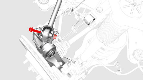
- Install and hand-tighten the bolt and nut that attach the rear bushing of the rear drive unit to the rear subframe.
.png)
.png)
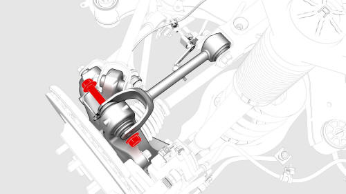
- Install and hand-tighten the bolt and nut that attach the RH bushing of the rear drive unit to the rear subframe.
.png)
.png)
- Install and hand-tighten the bolt and nut that attach the LH mount of the rear drive unit to the rear subframe.
- Lower the drive unit sling tool to release the tension on the cables.
- Remove the drive unit sling tool from the gantry.
- Remove the drive unit sling tool from the rear drive unit.
- Tighten the LH mount, RH bushing, and rear bushing
bolts and nuts that attach the rear drive unit to the
rear subframe.
 Torque 70 Nm
.png)
- Connect the electrical harness to the oil pump connector.
.jpg)
- Connect the electrical harness to the resolver connector.
- Remove the halfshaft plug from the gearbox, and then install the LH halfshaft to the rear drive unit. Note: New drive units come prefilled with gearbox fluid that might leak out of the drive unit during this step. Make sure to clean up any leakage. Note: Set the LH halfshaft on the aft lower control arm.
- Install the LH halfshaft to the hub and knuckle assembly.
.jpg)
- With an assistant, hand-tighten the bolt and nut that attach the LH toe link to the knuckle.
Note: The bolt and nut will be tightened to specification during the Four Wheel Alignment (Check and Adjust) at the end of the Front Subframe Assembly (Remove and Install) procedure.
- With an assistant, hand-tighten the bolt and nut that attach LH upper fore link to the knuckle.
Note: The bolt and nut will be tightened to specification during the Four Wheel Alignment (Check and Adjust) at the end of the Front Subframe Assembly (Remove and Install) procedure.
- With an assistant, hand-tighten the bolt and nut that attach the upper aft link to the knuckle.
Note: The bolt and nut will be tightened to specification during the Four Wheel Alignment (Check and Adjust) at the end of the Front Subframe Assembly (Remove and Install) procedure.
.jpg)
- Install the washer, and install a new nut to attach
the halfshaft to the LH rear hub.
.png) Torque 245 Nm
Torque 245 Nm
.jpg)
- Install the rear LH ABS wheel speed sensor to the
knuckle, and then install a new bolt to attach the
sensor to the knuckle.
.jpg) Torque 5 Nm
Torque 5 Nm
.jpg)
- Fasten the clip and install the grommet that attach the rear LH ABS wheel speed sensor cable to the rear LH knuckle and bracket.
Caution: Perform a push-pull check on the clip and grommet to make sure they are securely fastened to the knuckle and bracket.
.jpg)
- Connect the subframe harness to the rear LH ABS wheel speed sensor connector, and then fasten the clip that attaches the connector to the rear subframe.
- Repeat step 14 through 22 on the RH side of the rear drive unit.
- Fully raise the handle on the rear drive unit HV electrical harness.
.png)
- Attach the HV connector lever lock onto the back of the HV electrical harness.
- Firmly connect the HV electrical harness to the inverter connector.
Caution: Make sure that the harness fits the connector squarely and tightly.
- While pressing the harness to the connector, remove the HV connector lever lock.
.png)
- While pressing the harness to the connector, fully lower the handle.
.png)
- Slide the release to lock the HV electrical harness.
.png)
- Install the bolt that attaches the HV harness
bracket to the inverter.
.png) Torque 6 Nm
Torque 6 Nm
.png)
- Connect the rear drive unit inlet hose to the inverter coolant inlet, and then fasten the clip.
Caution: Perform a push-pull test to verify that the hose is fully seated.
.jpg)
- Fasten the clip that attaches the rear drive unit inlet hose to the HV harness bracket.
.png)
- Connect the electrical harness to the inverter low voltage connector.
.jpg)
- Fasten the clip that attaches the low voltage electrical harness to the inverter.
- Install the rear subframe assembly. See Subframe Assembly - Rear (Remove and Install).
READ NEXT:
 Drive Unit - Rear (Remove and Replace)
Remove
Remove the rear drive unit from the subframe
assembly. See Drive Unit - Rear (Remove and Install).
Mount - Rear Drive Unit - LH (Remove and Replace)
DRAFT
Warning:
This procedure was derived from pre-production computer
models, and might not reflect the real-world situation. Warning
SEE MORE:
Siren - Battery Backed (Remove and Replace)
Remove
Remove the front fascia assembly. See
Fascia - Front (Remove and Install).
Disconnect the connector from the battery backed siren.
Remove the bolt that attaches the battery backed siren to the front end
carrier, and then remove the siren from the vehicle.
Torque 12 Nm
Secure the Tires
The vehicle's tires must be secured onto the
truck using the eight-point tie-down method.
Ensure any metal parts on the tie-down
straps do not contact painted surfaces or
the face of the wheels.
Do not place tie-down straps over body
panels or through the wheels.
Caution: Attachi
