Tesla Model 3: Link - Lateral - Lower - Front - LH (Remove and Replace)
Tesla Model 3 2017-2026 Service Manual / Suspension / Front Suspension (Including Hubs) / Link - Lateral - Lower - Front - LH (Remove and Replace)
Remove
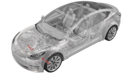
- Raise and support the vehicle. See Raise Vehicle - 2 Post Lift.
- Remove the LH front wheel. See Wheel (Remove and Install).
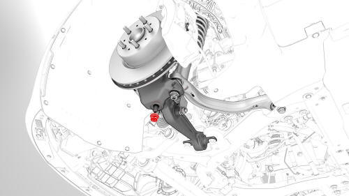
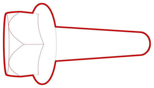
- Remove and discard the nut that attaches the LH front lower lateral link to the knuckle.
- Raise the vehicle fully.
- Remove the front aero shield. See Panel - Aero Shield - Front (Remove and Replace).
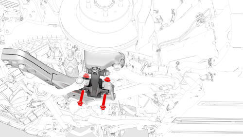
- Remove the bolts that attach the LH front lower lateral link to the subframe.
.jpg)
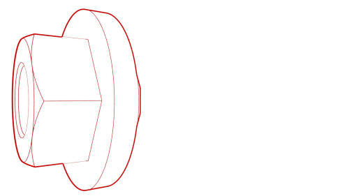
- Remove the bolt and nut that attach the LH strut to the LH front lower
lateral link, and then remove the LH front lower lateral link from the
vehicle.
Install
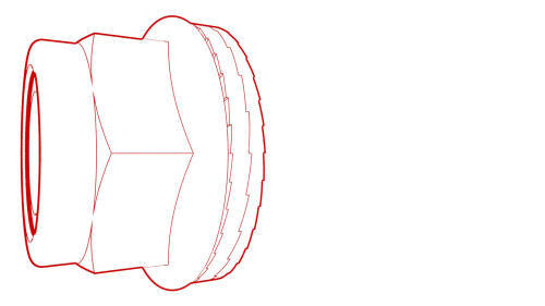
- Hand-tighten the bolt and nut that attach the LH strut to the LH front
lower lateral link.
.jpg) Torque 106 Nm
Torque 106 Nm
.jpg) Torque 106 Nm
Torque 106 Nm
Note: Tightening of the bolt and nut will occur during the four wheel alignment procedure.
- With an assistant, hand-tighten the bolts that attach the LH front lower lateral link to the front subframe.
Note: Use a punch tool to align the fasteners.
- Tighten the bolts that attach the LH front lower lateral link to the
front subframe.
 Torque 106 Nm
 Torque 106 Nm
 - Install the front aero shield. See Panel - Aero Shield - Front (Remove and Replace).
- Install a new nut to attach the LH front lower lateral link to the
knuckle.
 Torque 180 Nm
 - Install the LH front wheel. See Wheel (Remove and Install).
- Perform the four wheel alignment. See Four Wheel Alignment (Check and Adjust).
READ NEXT:
 Link - Stabilizer Bar - Front - LH (Remove and Replace)
Remove
Remove the LH front wheel. See
Wheel (Remove and Install).
Remove and discard the nuts that attach the front LH stabilizer bar link
to the stabilizer bar and damper, and then remove
Stabilizer Bar - Front (Remove and Replace)
Remove
Remove the front fascia valance. See
Valance - Front Fascia (Remove and Replace).
LH side shown, RH similar
Remove and discard the nuts that attach the front stabilizer bar to the
L
Suspension - Front (Check Torque)
Procedure
Remove the LH and RH front wheels. See
Wheel (Remove and Install).
Remove the front aero shield panel. See
Panel - Aero Shield - Front (Remove and Replace).
Remove the clips (x2) t
SEE MORE:
Forward Facing (Target Calibration)
SPECIAL TOOLS
Camera Calibration Target (1053066-00-A)
Wrench, 2.5mm, Thin (1448868-00-A)
Note: This procedure describes how to calibrate the forward
facing cameras. It does not apply to the rear facing camera.
Setup
Park the vehicle on a flat surface with at least 106 cm (3.5 ft) of
space in
Bracket - License Plate - Front (EMEA) (Retrofit using Template)
Procedure
Clean the front center surface of the front fascia.
Align the template with the parking sensors, and then use masking tape
to hold the template in place.
LH side shown, RH side similar
Align the front license plate bracket over the template, and then secure
the bracket
© 2019-2026 Copyright www.tmodel3.com
