Tesla Model 3: Procedure (Three - Phase) (China)
Tesla Model 3 2017-2024 Service Manual / High Voltage System / Charge System Inlet / Charge Port Voltage Check / Procedure (Three - Phase) (China)
- Open the charge port door.
- Disconnect 12V power. See 12V Power (Disconnect and Connect).
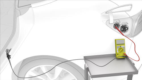
- Set the insulation multimeter to measure the DC voltage across the 12V auxiliary battery terminals.
Caution: If the voltage across the 12V auxiliary battery terminals is less than 10 volts or greater than 14 volts, the multimeter is not measuring reliably and must not be used. Use only a fully functional multimeter.
- Remove all loose articles and jewelry from your person.
- Put on safety glasses, High Voltage (HV) insulating gloves, and leather glove protectors.
- Prepare the insulation multimeter with slim test probes and alligator clips.
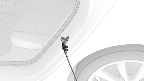
- Attach the black negative alligator clip to the LH rear door striker.
- Set the insulation multimeter to DC voltage.
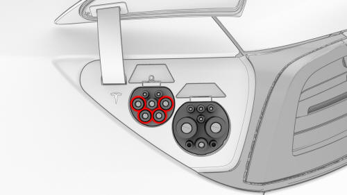
- Touch the red positive slim test probe to each of the lower 4 pin terminals of the charge connector highlighted in this illustration, and read the voltage:
- If a terminal voltage is less than 10V, measure the next terminal, until all are measured.
- If a terminal voltage is 10V or greater, stop this procedure and contact Service Engineering.
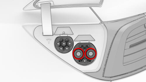
- Touch the red positive slim test probe to each of the terminals of the DC connector highlighted in this illustration, and read the voltage:
- If a terminal voltage is less than 10V, measure the other terminal.
- If a terminal voltage is 10V or greater, stop this procedure and contact Service Engineering.
- If all previous voltage readings were less than 10V, return to the procedure that specified the charge port voltage check
READ NEXT:
 Deadfronts - Pin - Charge Port (NA) (Remove and Replace)
SPECIAL TOOLS
Cap, Logic Conn, Inv, 3DU (1108272-00-B)
Test Pro
Door and Hinge Cover - Charge Port (Remove and Replace)
Remove
Open the charge port door.
Remove the 2nd row lower seat cushion. See Seat
Cushion - Lower - 2nd Row (Remove and Repl
SEE MORE:
Battery - 12V (Remove and Replace)
Remove
Remove the 2nd row lower seat cushion. See
Seat Cushion - Lower - 2nd Row (Remove and Replace).
Remove the rear underhood apron. See
Underhood Apron - Rear (Remove and Replace).
Remove the cabin intake duct. See
Duct - Cabin Intake (Remove and Replace).
Disconnect 12V power. See
12
Gearbox - Rear Drive Unit (Remove and
Replace)
Remove
Remove the rear drive unit
inverter. See
Inverter - Rear Drive Unit
(Remove and Install).
Setup the gantry to support
the gearbox motor assembly.
© 2019-2024 Copyright www.tmodel3.com
