Tesla Model 3: Vehicle Electrical Isolation Procedure
SPECIAL TOOLS
Insulation Multimeter, Fluke 1507 (1076921-00-B)
Test Probes, Slim, Fluke TP38 (1130480-00-A)
Warning: This procedure verifies that high voltage power is no longer available to high voltage components (PTC heater, A/C compressor, inverters, etc). Perform this procedure before servicing high voltage components.
Warning: Remove all jewelry (watches, bracelets, rings, necklaces, earrings, ID tags, piercings, etc.) from your person, and all objects (keys, coins, pens, pencils, tools, fasteners, etc.) from your pockets before performing any procedure that exposes you to high voltage.
Warning: If corrective eyewear is necessary to safely perform any procedure, make sure that the eyewear is securely restrained to the head and cannot fall off.
Warning:Only technicians who have been trained in High Voltage Awareness are permitted to perform this procedure. Proper personal protective equipment (PPE) and insulating HV gloves with a minimum rating of class 0 (1000V) must be worn at all times a high voltage cable, busbar, or fitting is handled. Refer to Tech Note TN-15-92-003, "High Voltage Awareness Care Points" for additional safety information.
Warning: Make sure that the insulation meter and leads are capable of handling at least 500V DC.
Procedure
- Disconnect 12V power. See 12V Power (Disconnect and Connect).
- Set the insulation multimeter to measure the voltage across the 12V auxiliary battery terminals.
Caution:
If the voltage across the 12V auxiliary battery terminals is less than 10 volts or greater than 14 volts, the multimeter is not measuring reliably and must not be used. Use only a fully functional insulation multimeter.
- Remove all jewelry and empty your pockets before continuing this procedure.
- Put on HV insulating gloves and leather outer gloves before continuing this procedure.
- Remove the HV probe cover. See Cover - HV Probe - HV Battery (Remove and Replace).
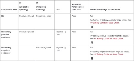
- Use the insulation multimeter to probe the voltages.
- Install the HV probe cover. See Cover - HV Probe - HV Battery (Remove and Replace).
- Return to the procedure that required the vehicle to be electrically isolated.
Note: After finishing the procedure that required the vehicle to be electrically isolated, perform a penthouse air leak test. See Penthouse Air Leak Test.
READ NEXT:
 Vent Hose - 12V Battery (Remove and Replace)
Remove
Remove the rear underhood apron. See
Underhood Apron - Rear (Remove and Replace).
Remove the cabin intake duct. See
Duct - Cabin Intake (Remove and Replace).
Remove the hood latch cover
Busbar - DCDC Ground (Remove and Replace)
Remove
Disconnect 12V power. See
12V Power (Disconnect and Connect).
Remove and discard the nut that attaches the DCDC ground busbar to the
HV battery at the DCDC passthrough.
Remove
SEE MORE:
Trim - C-Pillar - Rear - LH (Remove and Replace)
Trim - C-Pillar - Rear - LH (Remove and Replace) - Remove
Remove
Remove the 2nd row lower seat cushion. See
Seat Cushion - Lower - 2nd Row (Remove and Replace).
Remove the LH 2nd row seat side bolster. See
Bolster - Side - Seat - 2nd Row - LH (Remove and Replace).
Remove the LH side rail tr
Foam - Cushion - Driver Seat (Remove and Replace)
Foam - Cushion - Driver Seat (Remove and Replace) - Remove
Remove
Remove the driver seat. See
Seat - Driver (Remove and Replace).
Remove the driver headrest trim. See
Trim - Headrest - Driver (Remove and Replace).
Remove the side outer cover from the driver seat. See
Cover - Outer Side - Driv
