Tesla Model 3: Paint Defect Rectification
Note: This procedure was designed to be performed on flat or near-flat metal body panels with original factory paintwork. Any deviation from these circumstances can alter cutting times, tool speeds, and the ideal amount of pressure to be applied to the body panel. If uncertain about a defect, follow up with a paint correction expert.
Caution:
If performing paint correction on body lines, make the following adjustments:
- Sand paint inclusions only by hand.
- Apply less pressure to the body panel when cutting/polishing.
- Reduce cutting time from 15 seconds to 5 seconds at a time.
- Reduce buffer speed by 40-50%.
- Avoid excessive heat build-up.
- Do not let the compounds dissipate.
Determine Defect Risk Level
Inspect the defect(s) and determine whether they are low or high risk.- If the defect(s) are low risk, continue to the next step.
- If the defect(s) are high risk, escalate the repair to a body shop.
- Less than 1.5 mm diameter on flat or near-flat body panels
- Less than 1.0 mm diameter on or near character lines
- High or low spots
- Basic surface paint inclusions
- Holograms
- Swirls
- Solvent pop
- Overspray
- Light to medium depth scratches
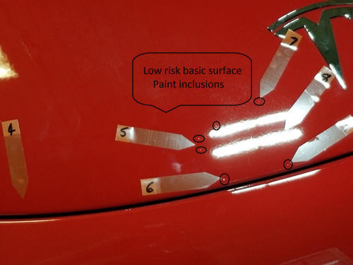
Low risk basic surface paint inclusions
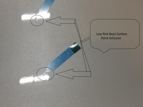
Low risk basic surface paint inclusions
- High Risk Defect Characteristics
- Larger than 2.0 mm diameter on flat or near-flat body panels
- Larger than 1.0 mm diameter on or near character lines
- Off color inclusions
- High or low spots larger than 2.0 mm
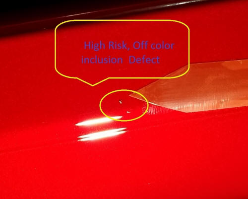
High risk off color paint inclusion
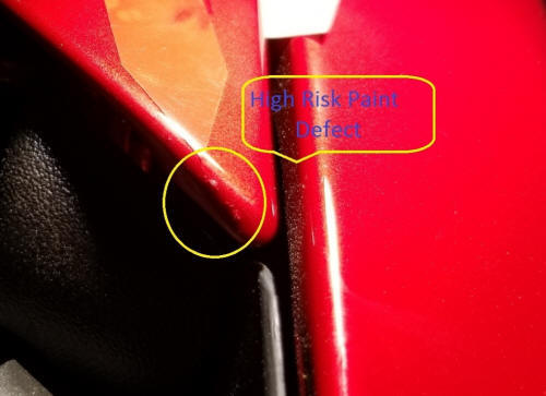
High risk defect on character line
READ NEXT:
 Remove Dirt Inclusion
Apply isopropyl alcohol to the general area of the defect, and then wipe
the area with a clean microfiber towel.
While wearing a nitrile glove, run hand over the area around the dirt
inclu
Polish
Remove the cutting pad from the buffer, and then install a polishing pad on
the buffer.
Apply 4 evenly spaced 20 mm diameter dollops of polishing compound on the
polishing pad.
Set the buffer speed
SEE MORE:
Shield - Dust - Brake - Rear - LH (Remove and Replace)
Shield - Dust - Brake - Rear - LH - Remove
SPECIAL TOOLS
Card, Magnetic Field Viewer (1062500-00-A)
Tool, Hub Puller, Hydraulic (1096075-00-A)
Remove
No
Connecting to Wi-Fi
Wi-Fi is available as a data connection method
and is often faster than cellular data networks.
Connecting to Wi-Fi is especially useful in
areas with limited or no cellular connectivity.
To ensure fast, reliable delivery of software
and map updates, Tesla recommends leaving
your vehicle c
© 2019-2026 Copyright www.tmodel3.com
